Posts: 133
Threads: 15
Joined: May 2009
I decided that my layout could work better with a transfer table as a staging area. While there are some resources available regarding the construction of these, there still are a few things seeming a bit problematic.
The first one is powering the table or rather only the active track (in case I want to use the table for engine storage; if the table is only going to be used for cars it could as well be always fully powered which probably simplifies things). Anyways, which is a good way of getting power to the traverser? I even thought of using a piece of mrr track which could both work as the roller (instead of using a drawer slide mechanism) as well as a power source (wire the track on which the transfer table runs as if it were a part of the layout), but whether it would work adequately is the question.
The second one is whether it might be necessary to hold cars in place on the transfer table (imagining that very smoothly rolling cars might start moving while manipulating the table (currently only considering a manually moved table, not sure how difficult or necessary it would be to power the table.) Or is it enough to make sure the layout is level (which is probably a very good thing in any case.)
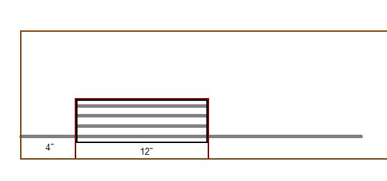
Attached is a sketch of the traverser - at the far end of the table there is a track which holds one engine so that it can be moved to the other end of the train for when the train is returning to the layout. Although I'm going to run steam engines, I didn't include a turntable here.

-norm
Posts: 6,193
Threads: 1,126
Joined: Nov 2008
Don't know whether this will help you - or confuse you   But....
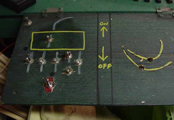
I built a yard, and made the "transfer part" a single track. I just ran wires to the tracks and built a small control station with "on / Off switches power to the diferent tracks and one for the transfer section and a DPDT switches (Center off) for the overall power to everything.
i was going to use string and some sort of motor, to move it, never figured that out yet ...
I guess wooden dowels would work in smaller scales, This one is in G

Posts: 6,193
Threads: 1,126
Joined: Nov 2008
Here is the panel.. The left side has the yard controls below the transfer track.

Posts: 133
Threads: 15
Joined: May 2009
Thanks!
So I take it that your transfer table is still manually operated then? Is there anything helping to easily align tracks? (working with n gauge so derailments might be possible here...read somewhere that filing the insides of the rails might help a little)
-norm
Posts: 931
Threads: 68
Joined: Dec 2008
Traversers - great subject! There are many ways of dealing with the sliding - railroad track with bogies, drawer runners, or my favorite - 2 pieces of K&S brass rectangular section 3/32" x 3/16", set on edge in the pit with some of their channel that looks like a flat-bottom U sliding on it (sorry, I don't have a bit with a lable so I can't tell you the size!) and fixed to the underside of the traverser - If you go through your LHS stock you will find ones that are a close sliding fit - I don't have a LHS so I got some rather strange looks at an exhibition going through a dealers stock - once I explained he was quite happy! Feed power to the rectangular section and take power to the traverser tracks via the U section. If you don't want all the tracks live, fit a sub-mini SPDT switch at the end of eack track away from the entrance, so the handle acts as a bumper, and aligned with the track so that the one that is live has the handle pointing along it. To fix the tracks so they are aligned, a strip of brass along the feeding end with a small ball catch in the end of the main board, centered between the feed track, and small holes in the brass strip centred between the rails will act as detents. Another, and simpler, method - a half inch piece of brass tube soldered to the OUTSIDE of each rail on the traverser and a one inch piece of the same size tube soldered to the OUTSIDE of the rails that feed stock onto the traverser from the layout. Suitable size wire, to be a sliding fit in the longer tube and bent into an L shape with the end of the longer leg tapered or rounded will act like a sliding cupboard bolt, and will hold the aligned track so that the traverser cannot move - and also transfer the power from the feed tracks to the aligned tracks. It is worth having a triangle shaped bit of plastic between the rails at the feed end of the rails on the traverser, and between the rails of the feed track itself - it will act as a re-railing guide and ensure the wheels track accurately across the join. The one thing I will stress - WHATEVER YOU USE FOR THE SLIDING MECHANISM MUST BE ABSOLUTELY SQUARE - IF IT IS FRACTIONALLY OUT THE TRAVERSER WILL JAM EVERY TIME! I don't want to be held responsible for your family hearing unseemly language! 
Posts: 2,458
Threads: 57
Joined: Dec 2008
Hi...I built a table just like that one to serve as a "fiddle" yard for incoming traffic to the layout. It's not "active" yet as tha layout is still in the building stage, but I made provisions to power every track (4) with a rotary switch. As it's kinda' hefty, I mounted it on drawer slides, and use an "indexing" bar held in place by a metal pin that aligns the tracks perfectly. On the transfer end I placed a rerailer sawn in half on every track to prevent any mishap from ocurring while crossing the gap between the table and the lead....
Gus (LC&P).
Posts: 6,193
Threads: 1,126
Joined: Nov 2008
In G - you don't have to an nearly accurate as you are going to have to build this.  I like the rotary switch idea )above)  
Yes - still manually operated - actually - it's an inspection pit now... But the traverse can still be moves side to side to access cars.
one more thing.. make sure to build this long enough to store all the cars 'on each track" that you'll need. For instance if you know you have 2 or 3 long cars, be sure to make the traverse table long enough for them to rest on..
decide on the amount of storage you'll need - before you decide on the 12" length...
....and yeah, my cars were rolling all the time, especially when someone 'bumped" the layout.. i had to buy "rail chocks". In the photo above, that's what that orange rail bumper is for, to stop the trolly from rolling onto the main..  
Posts: 133
Threads: 15
Joined: May 2009
I can already imagine how the brass slider system would look, will head to the LHS next week to see what they have in stock. Thanks for all your comments and ideas!
-norm
Posts: 2,410
Threads: 63
Joined: Dec 2008
Most of the ones I've seen are sector plates -- pivot around a bolt at the far end from the layout. Power arrangements vary, but a lot seem to have a pin (or nail) on the end of a lead which goes through a hole beside the desired track and both provides power and holds the table in alignment. usually the is for one rail and there is a pile of wire for the other one. This ensures that only the aligned track gets power.
David
Moderato ma non troppo
Perth & Exeter Railway Company
Esquesing & Chinguacousy Radial Railway
In model railroading, there are between six and two hundred ways of performing a given task.
Most modellers can get two of them to work.
Posts: 133
Threads: 15
Joined: May 2009
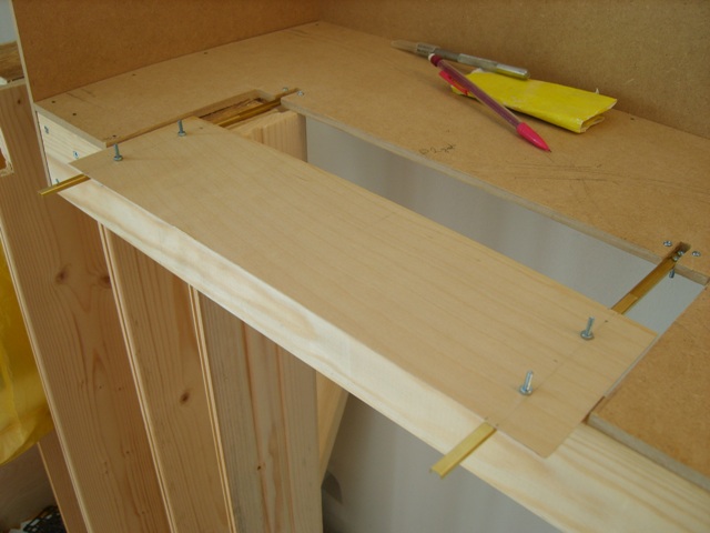
I went with shortliner's idea of using the K&S U-profiles and the warning of aligning everything correctly was very true - I even managed to BEND one of the profiles about 45 degrees which almost ruined the entire project (well, at least until I would get some more metal to replace it), but after twisting and bending it back into shape the damage is largely undone. It is a very close fit, but at least it can be moved back and forth without forcing it and it won't slide by itself, which is good. I might need to add a counterweight on the table side as the traverser is now loose and a heavy engine on the edge side might tip the traverser and everything on it into the abyss/ground.
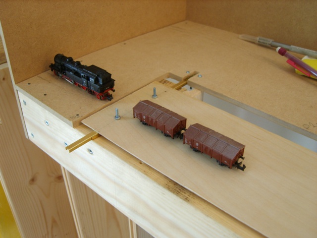
On the first picture you see how the traverser is intended to be used - on the far side there is room for the engine to uncouple (the BR78 on the picture is the longest one I intend to use on this layout), then the traverser can be moved to allow for the engine to move to the other side over an empty after which the traverser can be moved again so that the engine can pull the same train or another one stored on the two other tracks of the traverser onto the layout.

On the second picture the full length of the traverser and the abyss...

The track is due to be laid at the end of September.
-norm
Posts: 931
Threads: 68
Joined: Dec 2008
Looking forward to seeing your progress on this! 
Posts: 50
Threads: 0
Joined: Aug 2009
To get power to multiple tracks on the transfer table/traverser you could use ribbon cable similar to that used to hook the harddrive in your computer to the mother board (IDE cable), just make sure it's the easily flexed type and not the stiffer type. You could also use multi-conductor cable if you just let it hang down through the benchwork in a loop with both ends held tightly in a cable clamp. Just an idea.
Posts: 87
Threads: 4
Joined: Mar 2010
there are stepper motors with a screw drive available that can (with appropriate driver circuits) be accurate to less than 1/10th of a millimeter acuraccy repeatable
I built a winding machine for my old boss that was accurate to 99% to .1 of a millimeter for winding coils- it wouldn't be that hard to use a thread driven stepper motor to place a traverser
(it wouldnt be that hard to accurately position turntables either- a 256 step direct drive stepper motor should be way more accurate than ness- all it would take is the controlling electronics to do it...)
poopsie chicken tush
Posts: 87
Threads: 4
Joined: Mar 2010
<!-- m --><a class="postlink" href="http://www.oceancontrols.com.au/motor_controller/stepper_motor_controllers.htm">http://www.oceancontrols.com.au/motor_c ... ollers.htm</a><!-- m -->
an aussie stepper motor controller perfect for a screw driven traverse table or turntable- programmable from a pc using a pic or use an old pc to drive it
there should be something available anywhere else in the world you are that does the same job
poopsie chicken tush
Posts: 9,715
Threads: 233
Joined: Dec 2008
I have been watching my scanner while I scan slides, and I think if someone was very smart computer wise (not me) that a $30 scanner could be converted to operate a computer activated transfer table. Any thoughts?
Charlie
|


 I like the rotary switch idea )above)
