A new chassis for a Bachmann U33B
#1
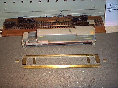
This is the start of the brass frame.
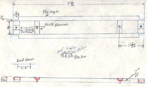
The frame rails are 7/32" x 7/32" angles cut to 7 11/16" and notched to clear the steps.
The end cross members are 3/16" x 3/8" rectangular tubing cut to 3/4".
The bolsters and coupler mounting pads are 1/4" x 1/8" channel.
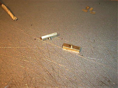
The king pins were turned on the lathe. They are 3/32" dia. and 1/8" long with a .050" high and 1/8" dia. head.
   

This is a crude drawing showing dimensions.


3/32" holes were drilled in the bolsters and the king pins were inserted and soldered in place.
   

The frame rails and end cross members were clamped to a piece of wood and soldered.
   

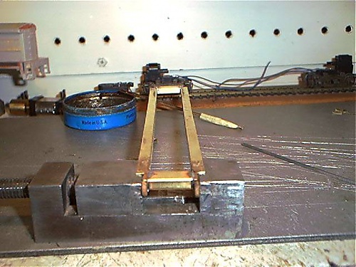
To solder the tops of the cross member, the frame was clamped in a vise with Popsicle sticks as insulators.
   
Ray Marinaccio
#2
The coupler mounting pads were then clamped in place and soldered.


016" shims were placed between the frame and the wood to get the correct bolster height. The bolsters were soldered in place with the king pin 1 13/32" from the end of the frame. A heat sink was used to keep the king pins from moving during soldering.

The trucks are 1973-1983 vintage Athearn trucks. They will be replaced with the 1980 and newer truck though because the mounting tabs for the metal side frames come to close to the frame and will short out on curves. Any GE or Alco 4 axle truck could be used by moving or modifying the bolster.


Frame with trucks installed.


Frame with shell installed.
Building the motor mount and fuel tank will follow as the project continues.


I swapped the trucks with another loco today and took measurements to calculate how far the motor needed to be recessed into the frame.
I'm using a Bachmann motor with mount I got in a parts lot.
The dimensions and possibly design of the mount may need to be different with a different choice of motor.
To figure out the depth of the mount I measured the distance from the bolster plate on the truck to the center line of the worm shaft. Then subtracted that from the measurement of the centerline of the motor shaft to the bottom of the motors mounting bracket. Then subtracted the measurement of the frame bolster to the bottom of the frame. This came out to be 3/16" below the bottom of the frame rail.
The one piece mount I designed will also include the frame floor and air tank hangers. It is made from .015" brass sheet.
A large hole will be drilled in the center of the mount to fill the fuel tank with ballast after it is installed.
There must be a .010" gap between the air tank hangers and the mount for the fuel tank to insert into.

This is a crude drawing of the mount. The red lines in the upper diagram are the fold lines.
I have the mount cut out and will get photos as I make the bends.

   
Ray Marinaccio
#3
After the dimensions were scribed onto a piece of .015" piece of brass sheet and cut out I began forming the bends. I started with the sides, clamping them between two 1/4" square bars in a vise and bending them over and flattening them out with a small hammer.


This shows the first two bends completed.


A 3/4" wide block was used for the next two bends.


The assembly was then clamped in the vise long ways as shown. The tops of the sides should be flush with the top of the vise. This will make the floor pannels higher than the sides so they will be up inside the frame rails. Then bend the ends down.

   
Ray Marinaccio
#4
The air tank mounting tabs were bent down as shown.


The holes were drilled and the air tank mounts were filed.


The assembly was then centered, clamped in place and soldered.


Here's a photo of the project so far.
The fuel tank will be next.


The motor is marked "Kader 881" , so I assumed it was a Bachmann.

These are the dimentions for the fuel tank.

   
Ray Marinaccio
#5
The two ends and tank wrapper were cut from .010" brass sheet.


The bends were formed starting from the inner bends and working outward.
The sheet was clamped between two 1/4" steel bars.


The first two bends completed.


The third bend in position ready to be folded.


Twisting the bars to make the bend.

   
Ray Marinaccio
#6
A 3/16" bar was used to make the final bends.


The completed wrapper.


The ends and wrapper were test fitted.
Some filing was required to get a good fit.


The parts were removed from the frame and the ends were soldered on at the bottom corners only.


The tank was refitted on the frame and the ends were soldered.

   
Ray Marinaccio
#7
Then the sides were soldered to the frame and then all the seams were soldered.


This is the frame after all the seams were filed.
The next installment will be the air tanks.


The air tanks were made from two 1" lengths of 7/32" brass rod (a float arm from a toilet).
The ends were shaped with a file as they turned in the lathe.
.020" holes were drilled in the ends for the air lines to be inserted into.
The tanks were then soldered to the mounts.


The fuel tank was filled with ballast (I used some shot from an old shotgun shell)then the filler hole was sealed with caulking.


The trucks and motor were installed and wired.

   
Ray Marinaccio
#8
Drive shafts were then fabricated.
I didn't have the Bachmann coupling so I fabricated the ball end and shaft then pressed it into an Athearn #90106 coupling that I drilled out and removed the spline from.
I would recommend using ready made universals from NWSL.


Once the shafts were installed it was ready for a test run.
Drilling the holes in the coupler mounts will be done after I finish the pilots to determine the correct location.
The air lines and Detail West fuel fillers will be added latter also.


At first it seamed a little noisy in the trucks.
Some cardstock shims on top of the square worm bearings quieted them down and its running great.

   
Ray Marinaccio
#9
This thread is a duplicate of one that we have over at our old forum's Academy. We've been wanting to do something we feel is important for quite a while. In the event anything were to happen to the old threads, we would lose a valuable resource, which in some cases would be lost forever, so we want to duplicate the old Academy here.

We have asked permission of all those responsible, for their content to recreate these threads in our New Academy. This and many other threads are being worked on by both our staff and the originators of these threads. Some threads show as being posted by, "Academy Staff". In these cases, the original poster is not registered on Big Blue but we have permission to recreate the thread here.

All threads in the New Academy are locked so if you want to comment on them, please do so in the proper forum, or PM the originator if he is registered here.
Don (ezdays) Day
Board administrator and
founder of the CANYON STATE RAILROAD


Forum Jump:


Users browsing this thread: 1 Guest(s)