03-15-2011, 06:01 PM
Hi again All.
Well here goes my first post on Big Blue which I intend to keep as concise as possible to prevent you moving on to something far more worthy of your valuable time. I just hope it makes sense.
To bring you up to speed and for reference purposes, there are four baseboards in total, each measuring 3' x 12", which I shall number 1 to 4.
Board#1 is a traverser which will probably carry four tracks (roads) to prevent grid lock during operation (if I ever finish it that is ). There's a picture or two of it under construction on my blog under the heading: 'A previous incarnation' <!-- m --><a class="postlink" href="http://www.rmweb.co.uk/community/index.php/blog/765-jontes-blog/">http://www.rmweb.co.uk/community/index. ... ntes-blog/</a><!-- m -->.
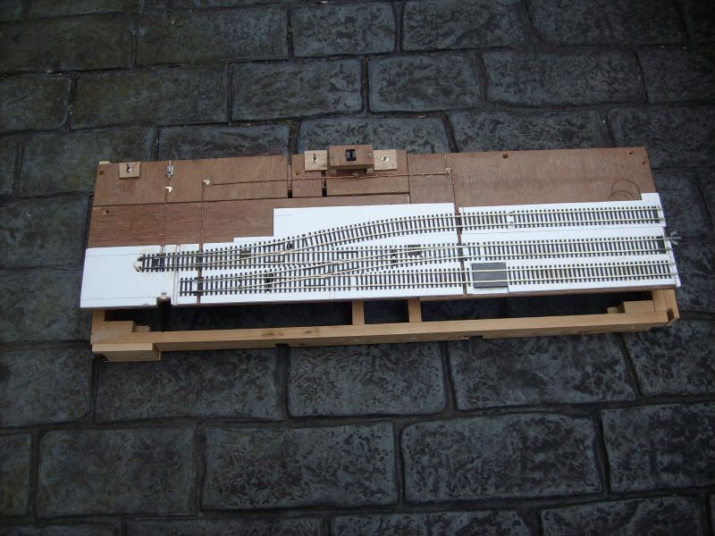
Board #2, is joined - yes you've guessed it - to board #1 and is the first of three scenic boards, the others being boards #3 & #4 respectfully. Beginning to bore myself now so here's a photo of Board #2 for your delectation:
This shows the general arrangement of things - a left handed crossover and lead to a long siding (team track?). There's a Kadee magnet buried in the underlay (foamboard, by the way, which has absolutuely no soundproofing properties which I didn't discover till I'd run the first piece of rolling stock across it - why did I use it? I'd loads of offcuts of the stuff left over from an aborted attempt to use it as the basis for constructing light baseboards which everybody seemed to advocate at the time - the less said about their robustness the better ). I didn't even reach the stage of topping them off before they began to bow
Just a further point before moving on: searching for a suitable plan for a switch style layout, with the proviso that anything suitable would have to contain a lefthanded crossover (after the blood, sweat and tears expended to lay, wire and operate them I had no intentions of dispensing with them) I discovered that it bore a vague resemblance to a plan entitled: Butley Mills, one of a number of plans published by the well known British railway modelling guru, Iain Rice, who I've since discovered has also had his works published on this side of the pond - it's just occurred to me that I keep using this term in the hope so I dearly hope that I don't cause offence, but if it does please let me know. Anyway, what was that about brevity??????
Moving on.
The crossover:
Peco Code 75 (Large radii) with the springs and containers removed to aid the use of my chosen method of point control - wire in tube. Why wire in tube? Well, it's cheap - I've done this on a shoestring budget - and it cuts down on the wiring - I also reckoned that if I practised hard enough, I could emulate the slow movement of those wonderful Tortoise units - again on the cheap - I can't believe I've even said that !!! Oh well, warts 'n all.....
I also took the liberty of reducing in length the diverging tracks of each point (switch) to facilitate a 6' way between parallel tracks. I'm pleased with the more prototypical look it imparts, however, this was at the expense of smoothness - this is just another example of me trying to run before I've learned to walk
The next two photos show the components of the wire in tube: incidentally, the crossover is controlled 'in tandem' by one lever only (from a Ratio signal kit) which, while extremely fiddly to put together, produced a rather pleasing result of which I'm quite proud - I really need to get out more.
Just one more and I'll leave you all in peace. This was one of the first 90* crossings I built for 'The Patch' a few weeks ago using all Peco Code 75 rail, purloined from one or two spare lengths of flexitrack. As you can see, the result is rather coarse to say the least, therefore, the ones used on the layout - which are of later construction - use Peco for the running rails and Code 75 Bullhead rail for the check rails which drastically slims down the appearance.
In the upper corners are the home made jigs used to construct the crossings and home made crossover which completes the runround loop and appears in my blog (will post some photos of it in situ in next couple of days). Simply made from bits of styrene and merely perform the role of maintaining 16.5 mm gauge between rails. To position the check rails, I simply wedged a short strip of PCB between check rail and running rail prior to soldering. Gaps a little wide, but 'Chessie' doesn't seem to like anything tighter
Anyway, that's all for now chaps - are there any lady members? - apologies if so.
Hope it's not too longwinded :oops:
More soon,
Jonte
Well here goes my first post on Big Blue which I intend to keep as concise as possible to prevent you moving on to something far more worthy of your valuable time. I just hope it makes sense.
To bring you up to speed and for reference purposes, there are four baseboards in total, each measuring 3' x 12", which I shall number 1 to 4.
Board#1 is a traverser which will probably carry four tracks (roads) to prevent grid lock during operation (if I ever finish it that is
Board #2, is joined - yes you've guessed it - to board #1 and is the first of three scenic boards, the others being boards #3 & #4 respectfully. Beginning to bore myself now so here's a photo of Board #2 for your delectation:
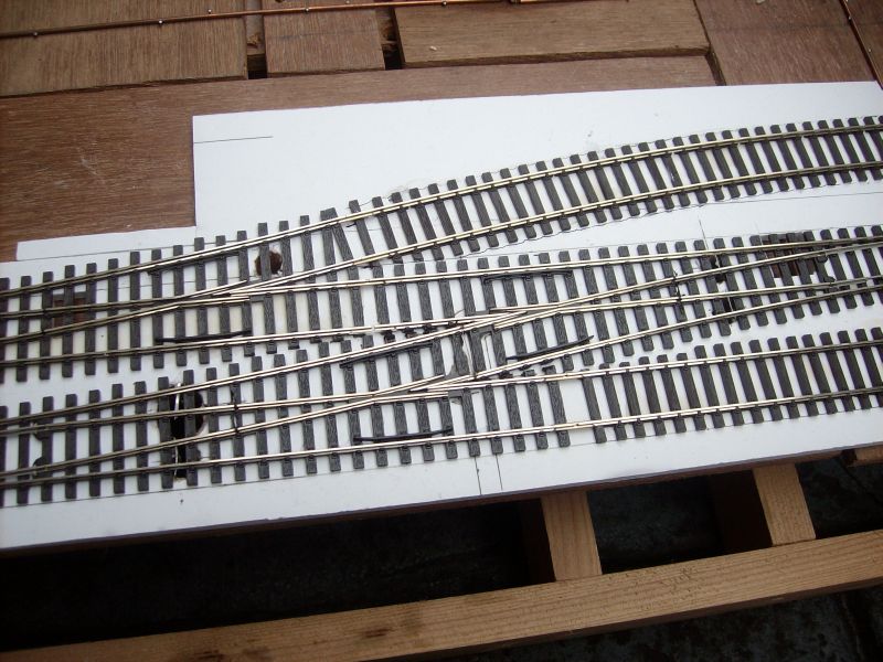
This shows the general arrangement of things - a left handed crossover and lead to a long siding (team track?). There's a Kadee magnet buried in the underlay (foamboard, by the way, which has absolutuely no soundproofing properties which I didn't discover till I'd run the first piece of rolling stock across it - why did I use it? I'd loads of offcuts of the stuff left over from an aborted attempt to use it as the basis for constructing light baseboards which everybody seemed to advocate at the time - the less said about their robustness the better
 ). I didn't even reach the stage of topping them off before they began to bow
Just a further point before moving on: searching for a suitable plan for a switch style layout, with the proviso that anything suitable would have to contain a lefthanded crossover (after the blood, sweat and tears expended to lay, wire and operate them I had no intentions of dispensing with them) I discovered that it bore a vague resemblance to a plan entitled: Butley Mills, one of a number of plans published by the well known British railway modelling guru, Iain Rice, who I've since discovered has also had his works published on this side of the pond - it's just occurred to me that I keep using this term in the hope so I dearly hope that I don't cause offence, but if it does please let me know. Anyway, what was that about brevity??????
Moving on.
The crossover:
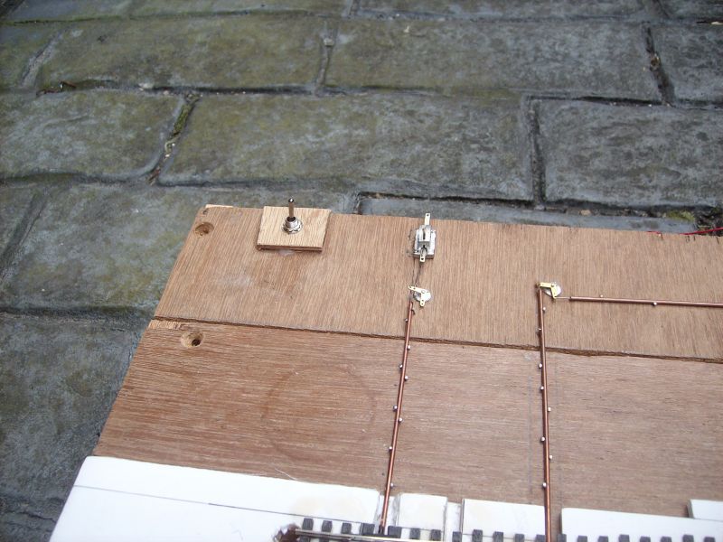
Peco Code 75 (Large radii) with the springs and containers removed to aid the use of my chosen method of point control - wire in tube. Why wire in tube? Well, it's cheap - I've done this on a shoestring budget - and it cuts down on the wiring - I also reckoned that if I practised hard enough, I could emulate the slow movement of those wonderful Tortoise units - again on the cheap - I can't believe I've even said that !!! Oh well, warts 'n all.....
I also took the liberty of reducing in length the diverging tracks of each point (switch) to facilitate a 6' way between parallel tracks. I'm pleased with the more prototypical look it imparts, however, this was at the expense of smoothness - this is just another example of me trying to run before I've learned to walk

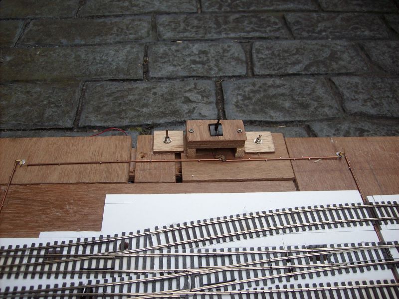
The next two photos show the components of the wire in tube: incidentally, the crossover is controlled 'in tandem' by one lever only (from a Ratio signal kit) which, while extremely fiddly to put together, produced a rather pleasing result of which I'm quite proud - I really need to get out more.
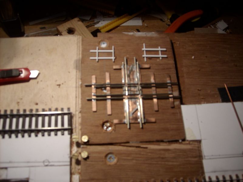
Just one more and I'll leave you all in peace. This was one of the first 90* crossings I built for 'The Patch' a few weeks ago using all Peco Code 75 rail, purloined from one or two spare lengths of flexitrack. As you can see, the result is rather coarse to say the least, therefore, the ones used on the layout - which are of later construction - use Peco for the running rails and Code 75 Bullhead rail for the check rails which drastically slims down the appearance.
In the upper corners are the home made jigs used to construct the crossings and home made crossover which completes the runround loop and appears in my blog (will post some photos of it in situ in next couple of days). Simply made from bits of styrene and merely perform the role of maintaining 16.5 mm gauge between rails. To position the check rails, I simply wedged a short strip of PCB between check rail and running rail prior to soldering. Gaps a little wide, but 'Chessie' doesn't seem to like anything tighter

Anyway, that's all for now chaps - are there any lady members? - apologies if so.
Hope it's not too longwinded :oops:
More soon,
Jonte


