02-04-2018, 02:05 PM
Here's a bit about the finger switch I was mentioning earlier.
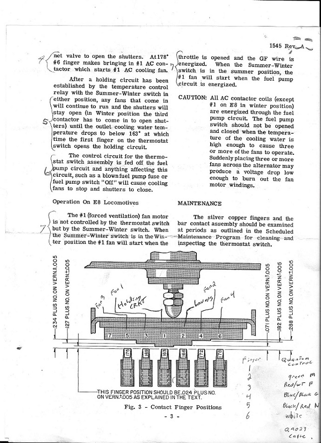
This is how the cooling fans on all F and E units were controlled as built by EMD/EMC ( except the FT's that had belt drives with manually controlled clutches ). A plunger attached to a set of contacts is placed on the cooling water outlet of the engine block. As the water heats up the plunger moves out in gauging the contacts (fingers). The hotter the engine, the more contacts get connected, the more fans come on. These contacts are calibrated to turn on fans in 3 degree steps. At 172 degrees the first fan comes on the next at 175 and so on. I have a diagram of the switch here.

This switch in our engine (664) is worn out and no longer working as it should. It sometimes binds and the contacts are pitted, this causes all sorts of engine cooling problems that's leads to the engine shutting down.
Here is a drawing/wiring diagram of the new controller. It's meant to be able to be used on several kinds locos with different numbers of fans and can also handle multi speed fans. So it takes a bit of reading and looking at charts to figure out how to set it up for our application.
This is how the cooling fans on all F and E units were controlled as built by EMD/EMC ( except the FT's that had belt drives with manually controlled clutches ). A plunger attached to a set of contacts is placed on the cooling water outlet of the engine block. As the water heats up the plunger moves out in gauging the contacts (fingers). The hotter the engine, the more contacts get connected, the more fans come on. These contacts are calibrated to turn on fans in 3 degree steps. At 172 degrees the first fan comes on the next at 175 and so on. I have a diagram of the switch here.
This switch in our engine (664) is worn out and no longer working as it should. It sometimes binds and the contacts are pitted, this causes all sorts of engine cooling problems that's leads to the engine shutting down.
Here is a drawing/wiring diagram of the new controller. It's meant to be able to be used on several kinds locos with different numbers of fans and can also handle multi speed fans. So it takes a bit of reading and looking at charts to figure out how to set it up for our application.
My other car is a locomotive, ARHS restoration crew


