Posts: 2,724
Threads: 160
Joined: Dec 2008
Moving onward, and back to the firebox.,,
The first thing I wanted to get to today is the front casting of the firebox. Most early camelbacks had straight fireboxes like this one shown here. ![[Image: cnj-s940.jpg]](http://www.rr-fallenflags.org/cnj/cnj-s940.jpg)
Latter on it was discovered that by lowering the forward edge of the firebox it became easier for the fireman (or men, some camels needed 2 ) to feed that cavernous belly. The modification also improved the draft over the coal thus improving efficiency as shown here. ![[Image: cnj-s0683dsa.jpg]](http://www.rr-fallenflags.org/cnj/cnj-s0683dsa.jpg) To do this required me to add just a little length to the forward casting or it just looks silly.

I also wanted to change the contour of the side of the fireman's shelter. The original one was a straight 90 degree angle, I was after more of a rounded sloping side.
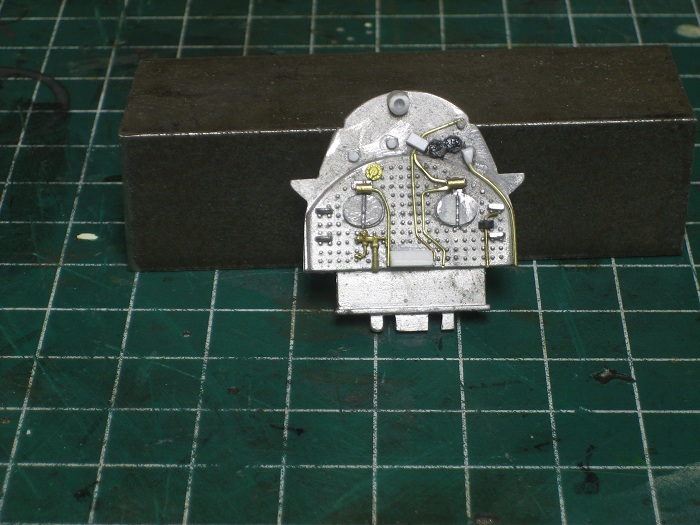
The edge was built up with styrene and sanded the the proper shape.
The next thing to get attention was the backhead.
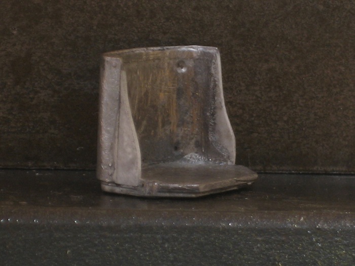
Here I added a work light at the top, a few gauges here and there, and a break valve on the right. The last thing the rear casting needed was to beef up the thin cross section at the bottom. This part will support some of the weight of the boiler and I wanted the castings that I make to have a little more strength, I just attached some styrene the the inside of the casting so my molds will have a thicker finished product.
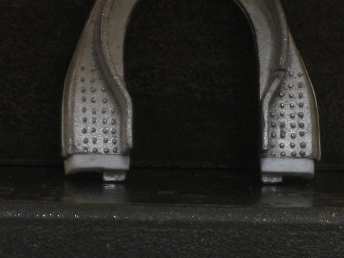
I've got a 3 day weekend coming up from work  so I'll be making molds of these parts then.
My other car is a locomotive, ARHS restoration crew
Posts: 1,682
Threads: 101
Joined: Dec 2011
Interesting story behing these engines. I personnaly never saw the old straight version.
I hope you will document your mold and cast process. I'm curious to see how you'll work your way out. BTW, are you building two camelback at the same time as your title implies?
Matt
Posts: 2,724
Threads: 160
Joined: Dec 2008
Will do Sailor. and yes I'm doing 2 at the same time. I have plans for 3 more camels, of different types, that will use the same molds that I will be making .
My other car is a locomotive, ARHS restoration crew
Posts: 1,682
Threads: 101
Joined: Dec 2011
e-paw Wrote:Will do Sailor. and yes I'm doing 2 at the same time. I have plans for 3 more camels, of different types, that will use the same molds that I will be making .
What are the wheel arrangements for the 3 other lucky ones?
Matt
Posts: 2,724
Threads: 160
Joined: Dec 2008
What are the wheel arrangements for the 3 other lucky ones?
A LNE 2-8-0, a freelanced 0-6-0, and a freelanced 2-8-8-0 or 2-6-6-2 haven't decided on that one yet, I was thinking of basing it on one of the old Mantua logging engine's.
My other car is a locomotive, ARHS restoration crew
Posts: 2,724
Threads: 160
Joined: Dec 2008
I started on my molds today. All of these castings will need a 2 part mold,, that's something that I haven't tried before. So It will be a learning experience for me too. I purchased a starter casting set from Micro-Mark and went to work on it.
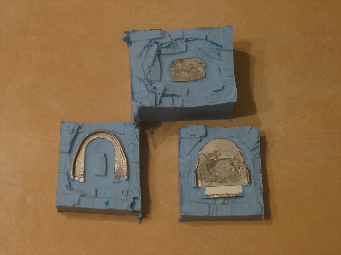
As per the instructions I formed some of the" KLEEN KLAY " into a rectangle and pressed the masters into it. Then with some $ store foam board I hot glued a box around each one, and tamped down the edges of the clay to make a good seal.
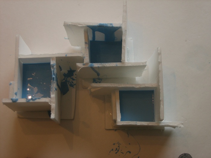
I then mixed up the 1 to 1 rubber and poured it into the form.
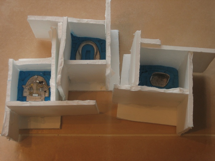
About 5 hours latter I broke apart the boxes and pulled the " KLEEN KLAY " free as carefully as I could so I didn't remove the master from the silicone. In a little bit I'll make the other side of the mold so I can cast tomorrow.
My other car is a locomotive, ARHS restoration crew
Posts: 446
Threads: 23
Joined: Mar 2009
I tried to help steve , e-paw, with some google searches. I found info on 6 Decaopd Camelbacks delievered to the NYLE&W, Listed as class J1. Later the Erie by Baldwin. First 5 were delievered in Dec 1891. These were numbers 800 to 804. The 6th made much later on for the World Columbian Exposition at Chicago in 1893. It was number 805. It was delievered to the Erie at the ending of the Exposition.
* In the following link. This is a book on the Exposistion. NYLE&W J1 2-10-0 camelback. Photo page 281.
<!-- m --><a class="postlink" href="http://books.google.com/books?id=It2xI5M9uQAC&printsec=frontcover&dq=World's+Columbian+Exposition+Chicago+1893&hl=en&sa=X&ei=wWYwT6ajKurf0QH_hOzjCg&ved=0CEAQ6AEwAA#v=onepage&q=World's%20Columbian%20Exposition%20Chicago%201893&f=false">http://books.google.com/books?id=It2xI5 ... 93&f=false</a><!-- m -->
* Another link. this opens to a copy of Engineering News 1893 Volume 29 page 558. Erie J1 2-10-0 camelback. first book.
<!-- m --><a class="postlink" href="http://books.google.com/books?id=buwRAQAAMAAJ&printsec=frontcover&dq=editions:jelCuxf-qXMC&hl=en&sa=X&ei=qnMwT-ndO8TW0QH0lfH1Cg&ved=0CEMQuwUwAzgK#v=onepage&q=editions%3AjelCuxf-qXMC&f=false">http://books.google.com/books?id=buwRAQ ... MC&f=false</a><!-- m -->
* Third link to "Engineering", Volume 57 Page 221. NYLE&W Decapod.
<!-- m --><a class="postlink" href="http://books.google.com/books?id=7FBQAAAAYAAJ&pg=PA221&dq=decapod+freight+locomotive&hl=en&sa=X&ei=a0tBT_O4HMPr0gGU_JHIBw&ved=0CEwQ6AEwAzge#v=onepage&q=decapod%20freight%20locomotive&f=false">http://books.google.com/books?id=7FBQAA ... ve&f=false</a><!-- m -->
toptrain steves dad.
" It's a Heck of a Day " !!!!
Posts: 720
Threads: 53
Joined: Dec 2008
What a beast! She's even a Vauclain Compound!
Michael
My primary goal is a large Oahu Railway layout in On3
My secondary interests are modeling the Denver, South Park, & Pacific in On3 and NKP in HO
<!-- m --><a class="postlink" href="http://thesouthparkline.blogspot.com/">http://thesouthparkline.blogspot.com/</a><!-- m -->
Posts: 2,724
Threads: 160
Joined: Dec 2008
As you can see in this pic I ran into a little trouble...  I didn't use enough mold release and the 2 halves of the molds fused together. One mold survived enough to be usable, but the other 2 will need to be recast.

So back to the workbench to make some new molds.
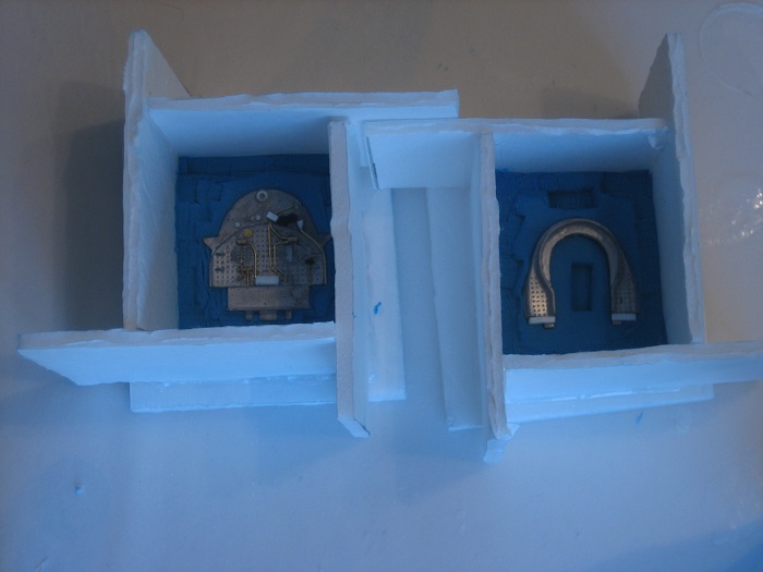
well here's the first run,
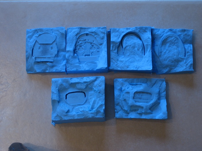
not bad for a first try. The still have some flash on then and the backhead casting is kind of thin, but it's a first try & I'm learning as I go. I'm going to cast at least 4 sets & pick the best ones for this project before I continue with the build.
My other car is a locomotive, ARHS restoration crew
Posts: 1,682
Threads: 101
Joined: Dec 2011
Nice, it's been years since I want to try casting my own pieces. I always like to see other do it! ;-)
BTW, the Decapod Camelback are going to be nice beasts!!!
Matt
Posts: 2,724
Threads: 160
Joined: Dec 2008
Now it's time to build the firebox section. The first thing I need to do is remove the flange from the forward firebox casting. Normally this lip would fit inside the back of the boiler, but in my case, the lip is the same diameter as the boiler. This means it has to go.
I measured & marked the lip as shown here and remover it with a hobby knife.
The two castings were squared off and glued to the boilers with CA type glue.
This glue joint is only temporary, something stronger will be necessary. you can also see that I also marked a center line down the length of the boiler and smokebox. This will help later in attaching things like the stack & domes. This line will also extend into the firebox.
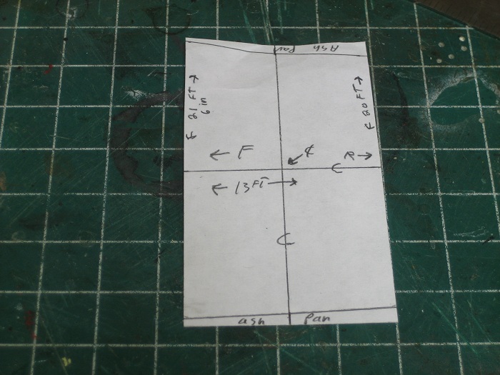
While the CA sets up I started on making a template from paper for the first layer of the firebox.
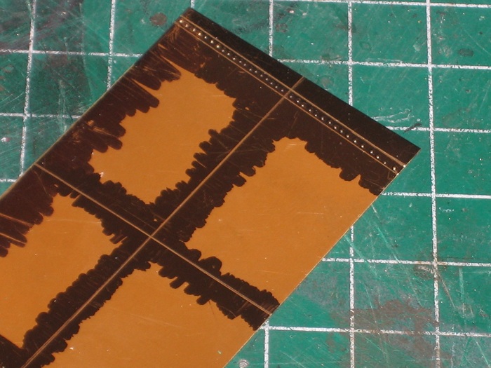
The markings on the template really help for lining up all the parts. They denote the front, rear, center, and fold lines for the ash pan supports. Once this was done I used the template to cut 2 sections of brass to match the template and transfer all the marks over to them. As shown in the next pic.
You'll also notice that I added a line if rivets just over the fold lines. This will become bottom section of the firebox that is unlagged. A layer of styrene will be added on top of the firebox latter to provide the bulk for the lagged upper portion. It will stop just short of the rivet line.
My other car is a locomotive, ARHS restoration crew
Posts: 2,724
Threads: 160
Joined: Dec 2008
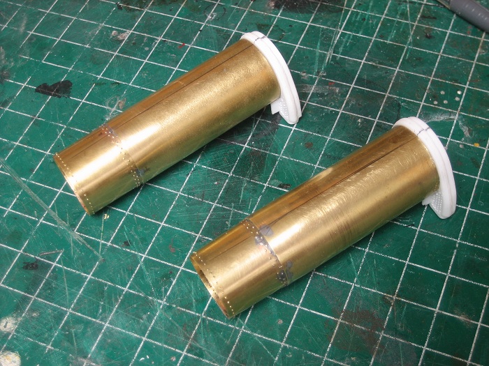
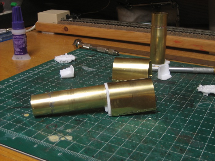
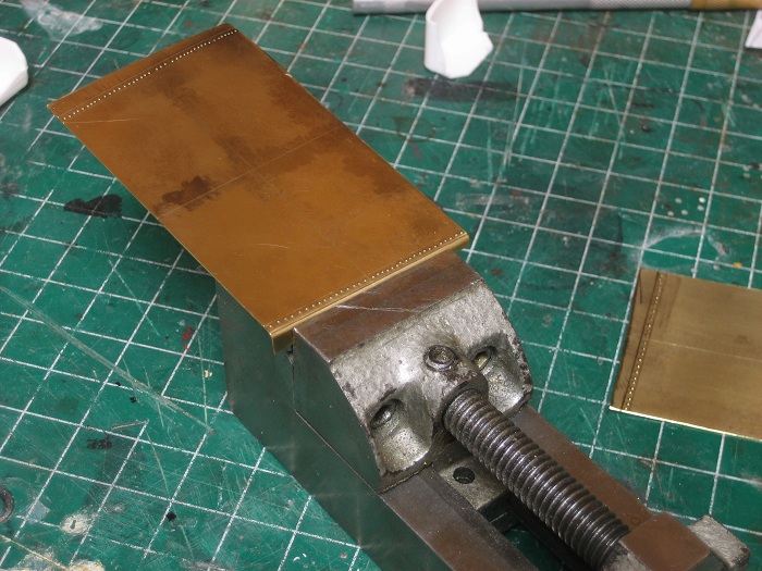
After all of that was finished it was time for me to bend the fold that would latter provide a place to mount my ash pans. I first cleaned off the ink that I had drawn on the brass with some rubbing alcohol. Then I locked it in a vice and bent the fold by hand until it was roughly at a 90 degree angle.
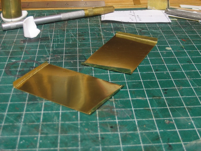
This was done at all 4 fold lines until I had this.
This fold will give me the sloping angle to the lower edge of the firebox that I am after.
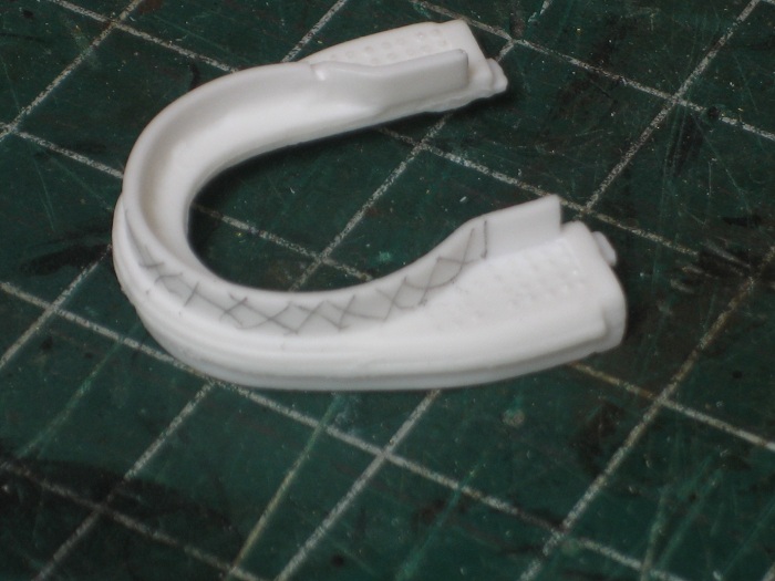
I next worked the brass sheet over the same dowel to form a rough curve. You just have to be patient and make small adjustments,,, straighten here, bend there, until it fits the profile of the forward casting. This can take some time but when your finished, use some more CA to glue it in place.
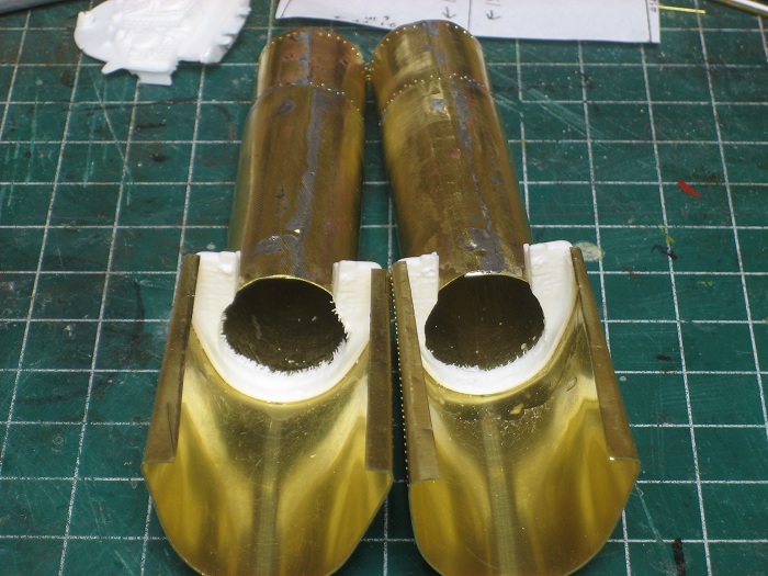
When the glue was dry I then had to make room for the drive. The casting was just to narrow for it to fit in there.
I took a round file and lightly worker the casting down to the same inside diameter as the boiler.
My other car is a locomotive, ARHS restoration crew
Posts: 5,859
Threads: 175
Joined: Dec 2008
Nice work, Steve, and nicely documented, too.  
Wayne
Posts: 990
Threads: 47
Joined: Jan 2009
Steve,
I'm very surprised how you build up these models doing very simple steps. Ok, there are many such steps with a few experiences - however all done in a logical sequence and a good progress. I'm looking forward seeing next pictures on way to finishing new and never before modeled engines.
I'm surprised about your courage starting such projects and I'm saluting to this. I never would start such an ambitious project. Wish you success, again!
Cheers, Bernd
Please visit also my website www.us-modelsof1900.de.
You can read some more about my model projects and interests in my chronicle of facebook.
Posts: 2,724
Threads: 160
Joined: Dec 2008
Thanks everyone. Now I really want to get the boilers mounted on the drives. Normally this is no big deal, I have always done this on older drives where there is only a motor & worm gear above the frame, but in this case the 2-10-0's are of a more modern split frame design. On the models there is a large open section on the underside of the boiler that clears the built in weight of the split frame. If I remove all the material on my boilers to fit this feature I will lose 90% of the soldered seam that holds the boiler round. I first thought of altering the frame, but this would result in a lot of milling and cutting that could result in changing the performance of the smooth running drive. Then I thought what if I sleeve the brass over plastic boiler and bond the 2 together with a high strength epoxy. This will insure that the brass boiler does not louse it's shape.
I striped all the detail parts off of the 2 boilers and cut off any parts that would protrude past the brass boilers. I will probably use some of the detail parts for this build on the new boilers,, It's freelanced so it can't be wrong.
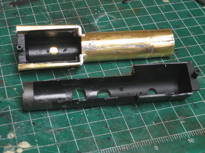
I will have to make some careful measurements of the opening before I glue them in, I'm a little concerned that I might mess up & cut the opening too large and ruin all that work up to this point.
Well a test fit proved that this will work out just right. This pic really shows the difference between a standard firebox and a Wooten type.
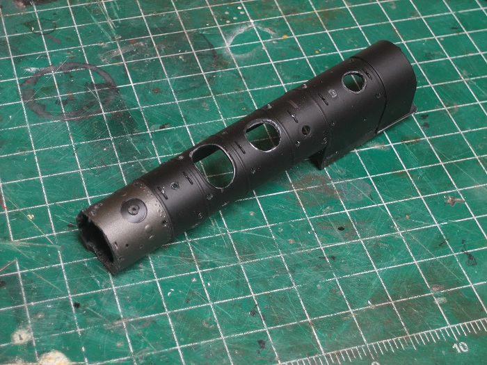
I'll pickup some epoxy tomorrow and get gluing when I get home from work. This will also give me a nice strong joint between the two brass sections of the new boiler, and the factory mount at the rear of the old firebox is now something that I do not have to fabricate. Once this is complete I can add the backhead casting. I think this should turn out well.
My other car is a locomotive, ARHS restoration crew
|
![[Image: cnj-s940.jpg]](http://www.rr-fallenflags.org/cnj/cnj-s940.jpg)
![[Image: cnj-s0683dsa.jpg]](http://www.rr-fallenflags.org/cnj/cnj-s0683dsa.jpg) To do this required me to add just a little length to the forward casting or it just looks silly.
To do this required me to add just a little length to the forward casting or it just looks silly.
 The edge was built up with styrene and sanded the the proper shape.
 Here I added a work light at the top, a few gauges here and there, and a break valve on the right. The last thing the rear casting needed was to beef up the thin cross section at the bottom. This part will support some of the weight of the boiler and I wanted the castings that I make to have a little more strength, I just attached some styrene the the inside of the casting so my molds will have a thicker finished product.
 I've got a 3 day weekend coming up from work
  so I'll be making molds of these parts then.
![[Image: cnj-s940.jpg]](http://www.rr-fallenflags.org/cnj/cnj-s940.jpg)
![[Image: cnj-s0683dsa.jpg]](http://www.rr-fallenflags.org/cnj/cnj-s0683dsa.jpg) To do this required me to add just a little length to the forward casting or it just looks silly.
To do this required me to add just a little length to the forward casting or it just looks silly. so I'll be making molds of these parts then.


 I didn't use enough mold release and the 2 halves of the molds fused together. One mold survived enough to be usable, but the other 2 will need to be recast.
