12-15-2008, 07:44 PM
Now that I got the speaker mounting sorted out I needed to figure out where to have the six wires needed exit the tender. Needed are 2 motor leads, 2 power leads as the front part of the locomotive will be picking up power from both rails and 2 wires for the headlight. I also had to decide if I was going to use micro plugs so the locomotive and tender could be seperated if needed.
There were two problems I could see if I used the micro plugs.
#1 was they are not rated for more than 500 mah. Okay for the headlight but not so good for the motor or the power feeds.
#2 Due to the design of the tender there was no space under the tender for them and no real good spot under the cab either. Even though they are micro plugs they are still fair sized so leaving them hanging between the tender and cab was not an option either.
I wanted an clean setup and to be honest I rarely seperate the tender from my plastic steam locomotives and they all have built in plugs. I decided to hardwire the tender to the locomotive in such a way I could still seperate them without to much hassle.
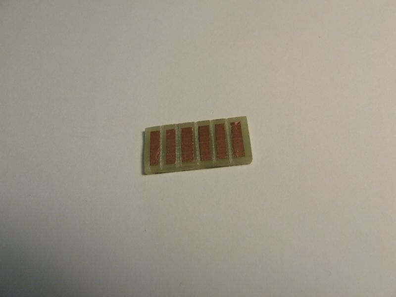
 Using a kit for making circuit boards and some single sided circuit board I made this little piece. It measures 1.2" x .5" and has 6 contact srtips. It started off as a piece of copper coated circuit board blank. Using 1/16 pinstripping I masked the copper areas I wanted to etch off with the acid included in the kit. I was left with 6 strips 3/32" wide which were painted over with clear lacquer to protect the copper. The pinstripping was then removed and the board placed in the acid. When it came out I was left spaces between the pads and around the perimeter of the board. I also filed a small grove with a small triangular file between each pad to make sure they were all isolated from each other.
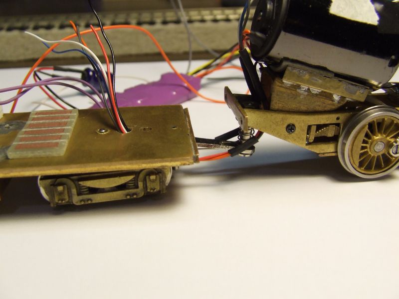
 To route the wires into the tender I drilled a 1/8" hole just in front of the front truck mounting point. The wires exit as two groups of three from under the cab and are routed one on each side of the draw bar. I would have liked to have them enter the tender closer to the tender front but due to the design of the tender front wall and a mounting screw for the tender shell being in the way this was my best option.
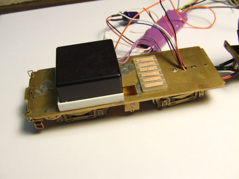
 This photo shows the speaker sitting in place and the circuit board I made. The circuit board will be stuck to the tender floor with some double sided tape in the postion shown in the photo. The six wires from the decoder will each be soldered to one end of each of the copper strips. The wires coming up through the tender floor from the locomotive will go the the other end of the copper strips. All the wires from the locomotive have been color coded to match the decoder wires.
If I ever need to seperate the tender I will just have to remove the tender shell and unsolder from the circuit board the six wires from the locomotive and pull them down through the hole. For safety the circuit board will be covered with some tape once the connections are made. No exposed contacts for this guy.
The decoder will be placed in the top of the tender shell up in the oil bunker. The wires between the locomotive and tender will be painted black so they look like hoses.
Wayne R
There were two problems I could see if I used the micro plugs.
#1 was they are not rated for more than 500 mah. Okay for the headlight but not so good for the motor or the power feeds.
#2 Due to the design of the tender there was no space under the tender for them and no real good spot under the cab either. Even though they are micro plugs they are still fair sized so leaving them hanging between the tender and cab was not an option either.
I wanted an clean setup and to be honest I rarely seperate the tender from my plastic steam locomotives and they all have built in plugs. I decided to hardwire the tender to the locomotive in such a way I could still seperate them without to much hassle.
If I ever need to seperate the tender I will just have to remove the tender shell and unsolder from the circuit board the six wires from the locomotive and pull them down through the hole. For safety the circuit board will be covered with some tape once the connections are made. No exposed contacts for this guy.
The decoder will be placed in the top of the tender shell up in the oil bunker. The wires between the locomotive and tender will be painted black so they look like hoses.
Wayne R


