09-09-2011, 04:06 PM
Thanks for the comments everyone. I have completed a little more work to the bridge, so DH draw is now back in an active build state again. 
First off, I measured, measured, and remeasured where my tracks were going to be located and then measured yet once again, (just to be sure). Once I was satisfied with the location of the mains I drew them out on the Foam board that I had used earlier. This gives me a good visual reference to where they are in relation to the center line of the bridge, In this case, the lift section.With a few pins I tacked down the movable section to the board and added girders to support the ties and track.
Each one was carefully cut, filed and glued in with CA to insure the tightest fit possible.( I really want to avoid having A heavy mike or train master splashing down into the river.
While that dries I went to work on the track...In general, the track that crosses bridges has a closer tie spacing than other track. My solution was to flip the track over and cut out the tabs between the ties on some flex track and slide them closer together. This pic shows the finished product compared to a standard section of track.
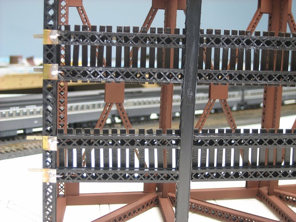
With that finished, the track was centered and secured to the bridge with more CA. Because this section will be movable I needed a way to get power to the rails. Feeders were soldered to the rails and then soldered to brass shims glued to the under side of the bridge with,,, yet more CA. When the bridge is in the closed position they will make contact with some other live contacts to complete the circuit. This was done at both ends to insure good power to the lift section.
My other car is a locomotive, ARHS restoration crew


