06-24-2013, 05:42 PM
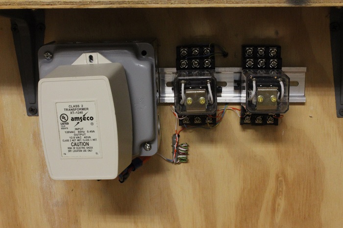
I used a small section of DIN rail to mount the two relays to a piece of plywood under my layout. At this time I have wired the two coils to work off the same switching circuit and I have wired the to local throttles to the relay on the left. The other will be for the signal circuit that still needs to be completed.
 The coils that activate the relays are powered by the transformer to the left. It's secondary side is 12 volt AC. I installed a bridge rectifier under it to convert the output to DC.
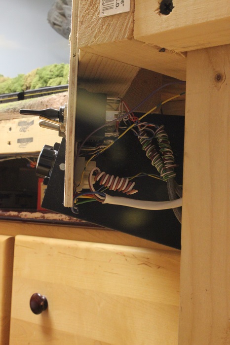
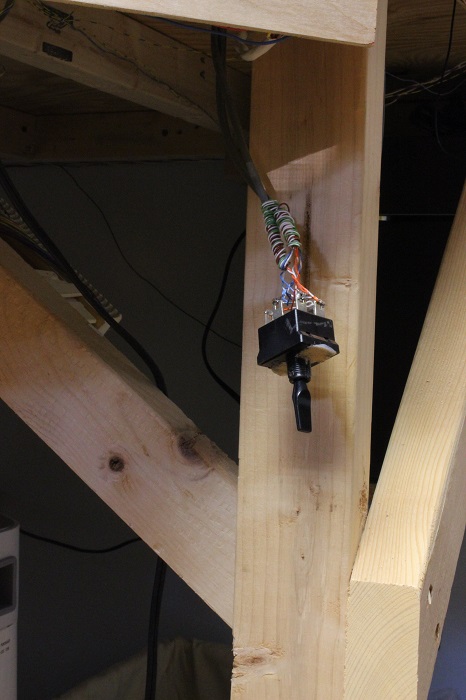
In Easton two wires are run to the switch. One comes from the relays and the other go's to the other switch in Bath. It is now back in it's original position.

I did make a quick video to show the relays operation.
![[Image: th_005-1.jpg]](http://i840.photobucket.com/albums/zz328/gronku2/the%20gauge/th_005-1.jpg)
![[Image: th_005-1.jpg]](http://i840.photobucket.com/albums/zz328/gronku2/the%20gauge/th_005-1.jpg)
For some reason the video posts twice I tried a few times to fix it but, no good. So watch it twice it you like .
.
In Easton two wires are run to the switch. One comes from the relays and the other go's to the other switch in Bath.
I did make a quick video to show the relays operation.
![[Image: th_005-1.jpg]](http://i840.photobucket.com/albums/zz328/gronku2/the%20gauge/th_005-1.jpg)
![[Image: th_005-1.jpg]](http://i840.photobucket.com/albums/zz328/gronku2/the%20gauge/th_005-1.jpg)
For some reason the video posts twice I tried a few times to fix it but, no good. So watch it twice it you like
 .
.
My other car is a locomotive, ARHS restoration crew


