02-04-2018, 01:07 PM
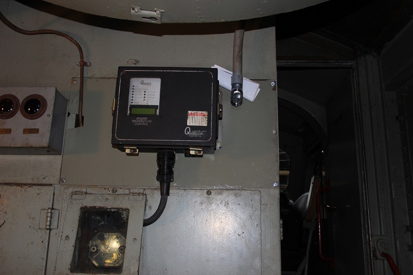
The new cooling fan control was mounted on the rear of the main electrical cabinet. I temporally ran the cable through the door for the ground fault reset, when I get the proper fitting I will drill out a hole next to the controller for it to pass through.

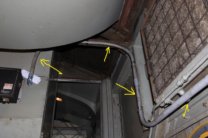
I also ran some new conduit from the same cabinet to get wire to the fan control cabinet at the rear of the loco.

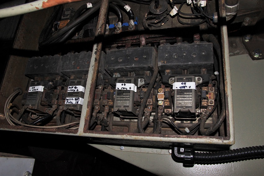
At the fan cabinet I tested all the contactors as we were having some problems with the fans not coming on. The four contactors are numbered 1 to 4 from left to right they handle the operation of the four fans , 1 in the front to 4 in the back. I found that the #1 contactor was not always getting signal to pull in, and the coil in the #2 contactor was bad so it would never pull in. The problem with the #1 fan is caused by a bad finger switch ( I'll go into that latter) It will be fixed with the new controller. The coil in the #2 contactor will need to be replaced.

By the way The "NFG" label on the #2 contactor Is an Italian abbreviation used in the electrical industry. It stands for " NOO FARGIN GOUD ". These labels will help us stay on track as another government shutdown is being expected by the end of the week.
The cable that leads into the cabinet ends at a terminal block shown here.
The power terminals at the top will go to a fuse and the fan and shutter wirers will be run to the fan cabinet.
I also ran some new conduit from the same cabinet to get wire to the fan control cabinet at the rear of the loco.
At the fan cabinet I tested all the contactors as we were having some problems with the fans not coming on. The four contactors are numbered 1 to 4 from left to right they handle the operation of the four fans , 1 in the front to 4 in the back. I found that the #1 contactor was not always getting signal to pull in, and the coil in the #2 contactor was bad so it would never pull in. The problem with the #1 fan is caused by a bad finger switch ( I'll go into that latter) It will be fixed with the new controller. The coil in the #2 contactor will need to be replaced.
By the way The "NFG" label on the #2 contactor Is an Italian abbreviation used in the electrical industry. It stands for " NOO FARGIN GOUD ". These labels will help us stay on track as another government shutdown is being expected by the end of the week.
The cable that leads into the cabinet ends at a terminal block shown here.
The power terminals at the top will go to a fuse and the fan and shutter wirers will be run to the fan cabinet.
My other car is a locomotive, ARHS restoration crew


