01-24-2023, 08:03 PM
PART 2, Scene 3 - Time to burn them wires
Knowing where the decoder is going to sit is a big key to a successful DCC integration. Now I know how long my individual wires need to be to reach from the decoder to the individual components (track pickups, motor pickups, lights). I do want to have some play in all of the wires so that I can remove the wiring harness from the decoder and push it through the hole in case I need to remove the shell of the locomotive. I figure a half-inch to an inch should work for that. I can always take the extra up into the space below the dynamic brake fan.
While I solder connections at components, I'll want to disconnect the harness from the decoder.
The first connection I want to make is soldering to the end tabs of each motor pickup. The top (positive) pickup will get the orange wire, the bottom (negative) pickup will get the gray wire in the harness. The motor housing has plastic parts, so to avoid some potential melt, I'll remove each pickup, solder to it, and reinstall it. I'll reinterate - there's a spring under each of the pickups that will do what springs do when they're released. Capture it and put it aside until you're ready to reinstall the pickup.

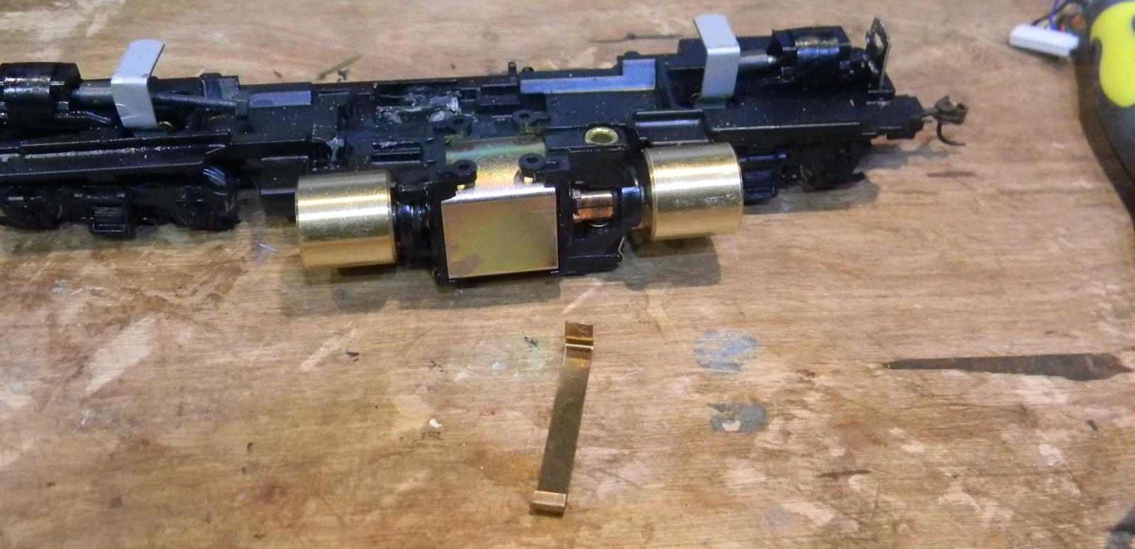
The photo above shows the lower motor pickup removed from the motor. The brass ring on the motor is where the magic spring will be coming from.

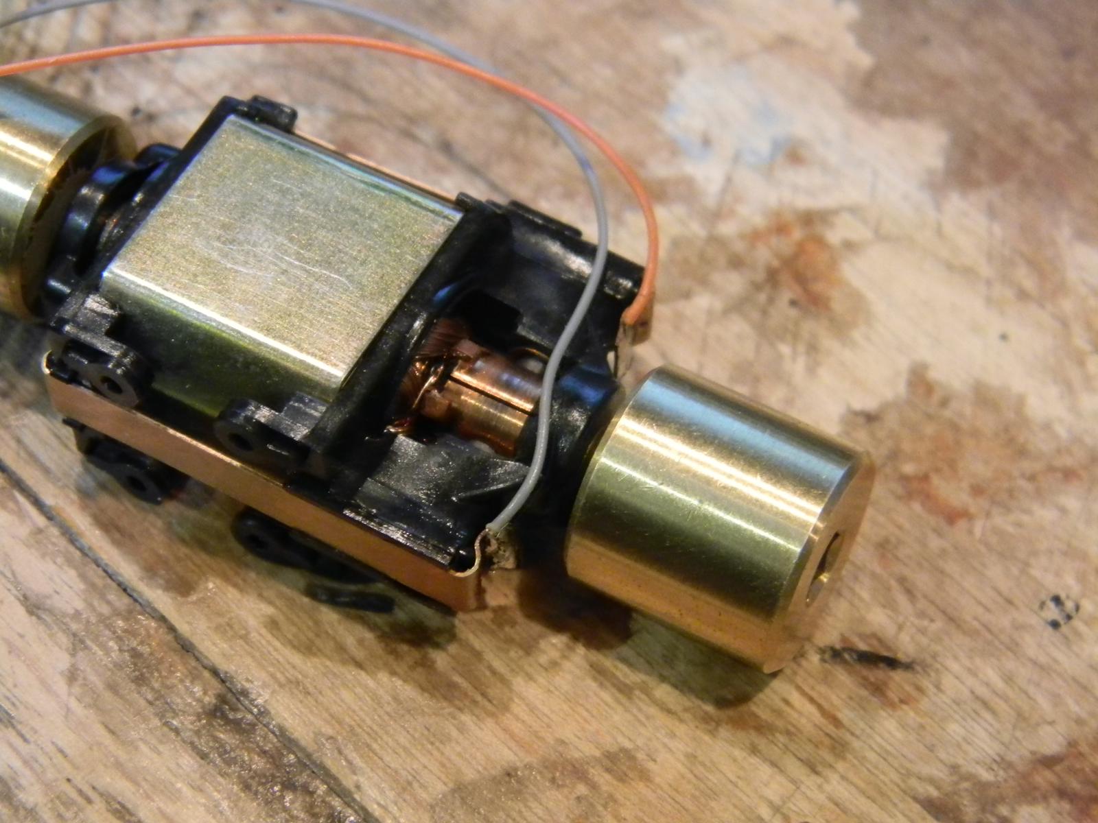
Wires have been soldered on the motor pickups at the end "pull" tabs.

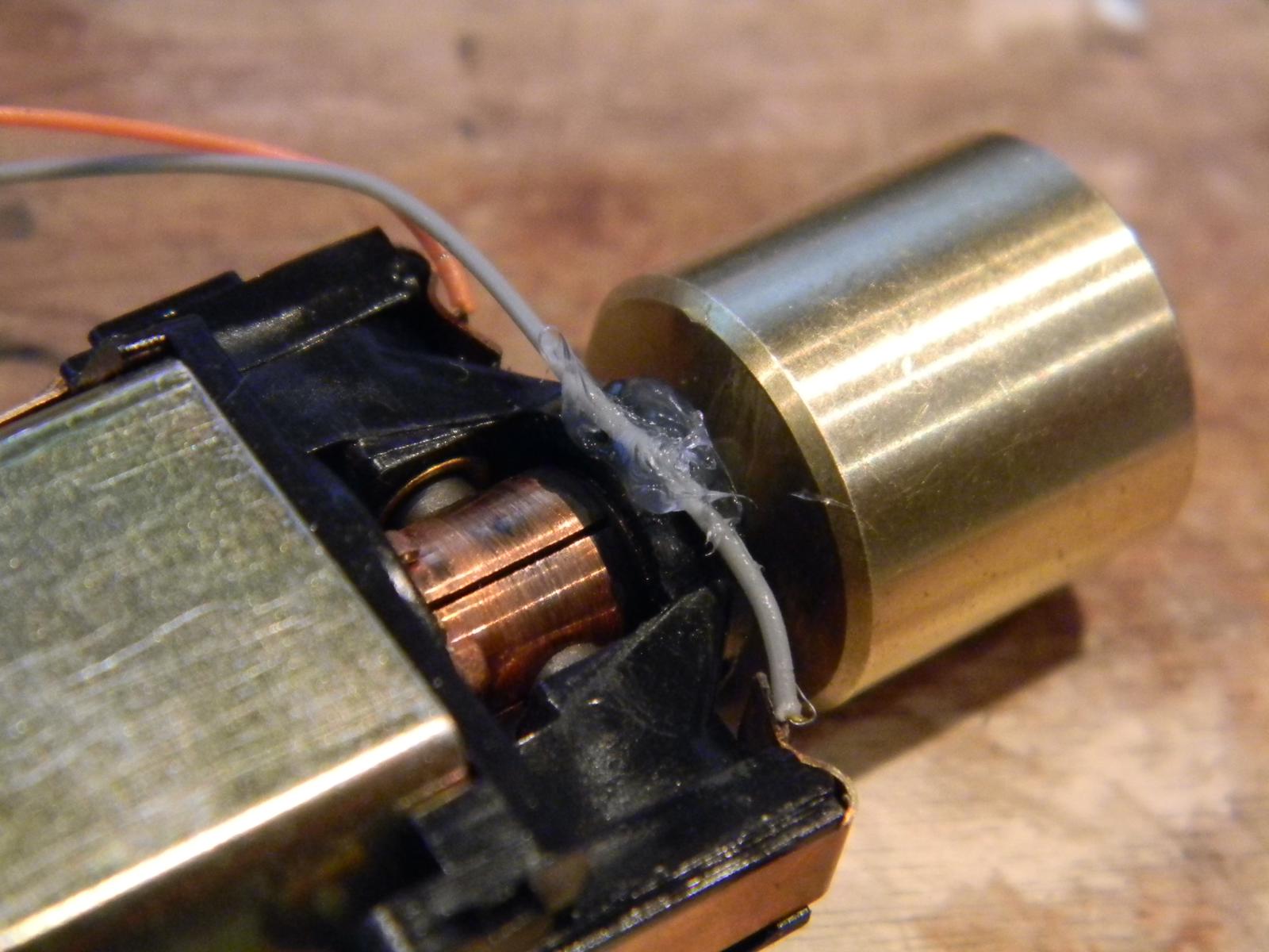
I've routed the wires and put a bead of silicone on the motor housing to keep the gray wire out of the motor. I'll let the silicone setup until tomorrow when I'll attach the leads to the track pickups coming from the trucks.
Knowing where the decoder is going to sit is a big key to a successful DCC integration. Now I know how long my individual wires need to be to reach from the decoder to the individual components (track pickups, motor pickups, lights). I do want to have some play in all of the wires so that I can remove the wiring harness from the decoder and push it through the hole in case I need to remove the shell of the locomotive. I figure a half-inch to an inch should work for that. I can always take the extra up into the space below the dynamic brake fan.
While I solder connections at components, I'll want to disconnect the harness from the decoder.
The first connection I want to make is soldering to the end tabs of each motor pickup. The top (positive) pickup will get the orange wire, the bottom (negative) pickup will get the gray wire in the harness. The motor housing has plastic parts, so to avoid some potential melt, I'll remove each pickup, solder to it, and reinstall it. I'll reinterate - there's a spring under each of the pickups that will do what springs do when they're released. Capture it and put it aside until you're ready to reinstall the pickup.
The photo above shows the lower motor pickup removed from the motor. The brass ring on the motor is where the magic spring will be coming from.
Wires have been soldered on the motor pickups at the end "pull" tabs.
I've routed the wires and put a bead of silicone on the motor housing to keep the gray wire out of the motor. I'll let the silicone setup until tomorrow when I'll attach the leads to the track pickups coming from the trucks.
Check out my "Rainbows in the Gorge" website: http://morristhemoosetm.wixsite.com/rainbows


