Posts: 2,724
Threads: 160
Joined: Dec 2008
On to the next one,,,, 
For the "part 2" I will be doing improvements to on my layout to the city of Easton PA. According to my "new Project", thread the last time I did any work to Easton was Aug. 2012...But that is not why I am calling it an orphan. Although the town is firmly set on the layout and connected to the main by a branch line, the track-age is completely inaccessible because of a few operational problems. This keeps it isolated from the rest of the layout and a true orphan.
The things I hope to accomplish are that I need to install and some manual switch, and some remote ones also, as some turnouts are out of reach. One of the biggest problems is that I need a way to switch control of the Easton track-age from one part of the layout to another. Most of the track needs ballast, I only did a few small sections when I was taking pictures for my RMC article. Not all of the blocks are connected and some more track needs to be laid to complete another connection to the main.
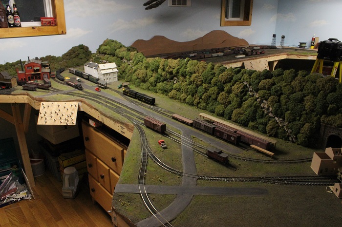
My problem is that Easton ( shown here)
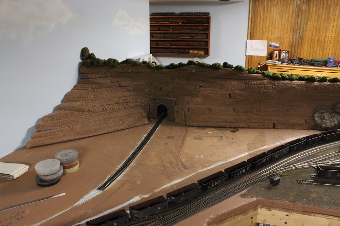
is a separate city that is serviced by the CNJ. It connects to the SH&D main at Allentown (shown here)
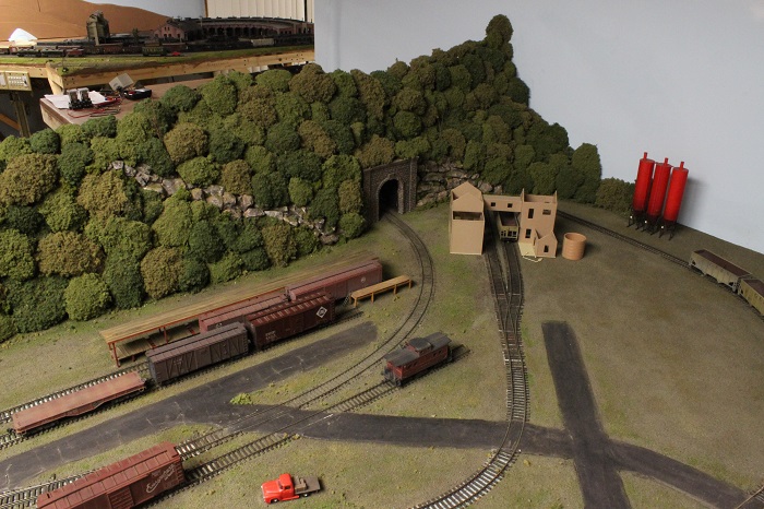
The branch starts at the switch with the track leading behind the mountain. The first two turnouts that the branch hits are out of easy reach, so remote switch machines are in order.( shown here )
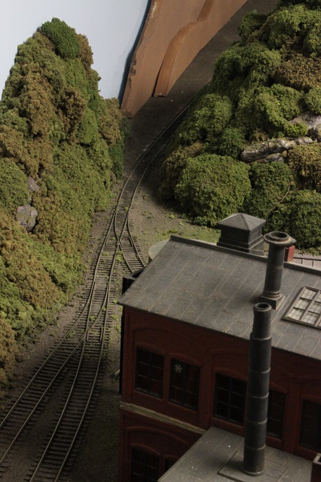
Also all the track leading up to that switch is dead. At the other (west) end of town the track ties into another railroad. The Bangor & Easton is the section of that turns off into the tunnel portal.( shown here )
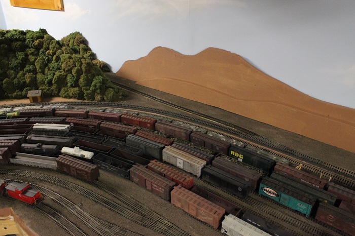
It is supposed to connect back to SH&D rails on the other side of the mountain in Bath. But some one has stolen the track  hock: .
My other car is a locomotive, ARHS restoration crew
Posts: 2,724
Threads: 160
Joined: Dec 2008
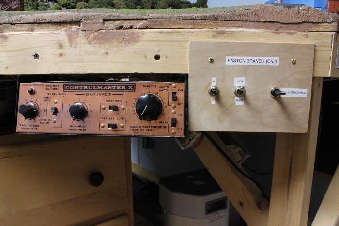
My mains are controlled by two walk around cabs, while yards, terminals, etc. have a local cab option as well as the walk rounds. like this...
mounting the switch that is labeled as B&E interchange is all that I have done in the way of getting my control problem taken care of.
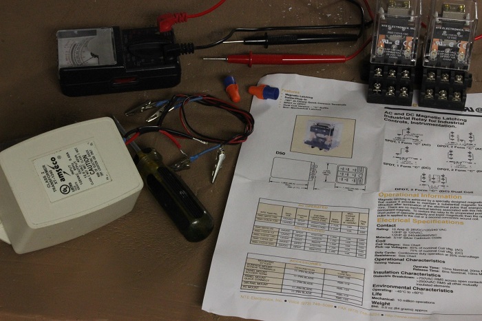
Because of the view block "mountain", I need a way to give control of a train from the local cab in Easton to the local cab in Bath. So after some thinking I decided to add two DPDT latching relays to the local cab circuit between the towns. A momentary DPDT switch mounted in each location will control the relays coil. That way train control can be passed back and forth from either location.
one relay will handle the track power and the other will operate a set of indicator lights denoting witch cab has control of the local territory. I'll probably use two dwarf signals mounted on the layout as my indicators.
My other car is a locomotive, ARHS restoration crew
Posts: 2,724
Threads: 160
Joined: Dec 2008
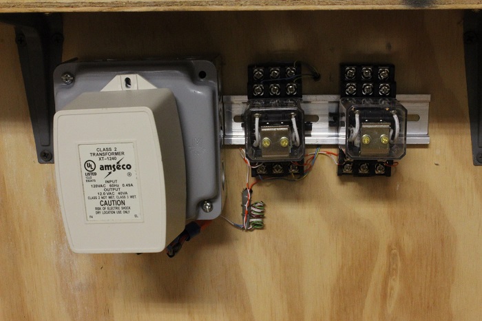
I used a small section of DIN rail to mount the two relays to a piece of plywood under my layout. At this time I have wired the two coils to work off the same switching circuit and I have wired the to local throttles to the relay on the left. The other will be for the signal circuit that still needs to be completed.
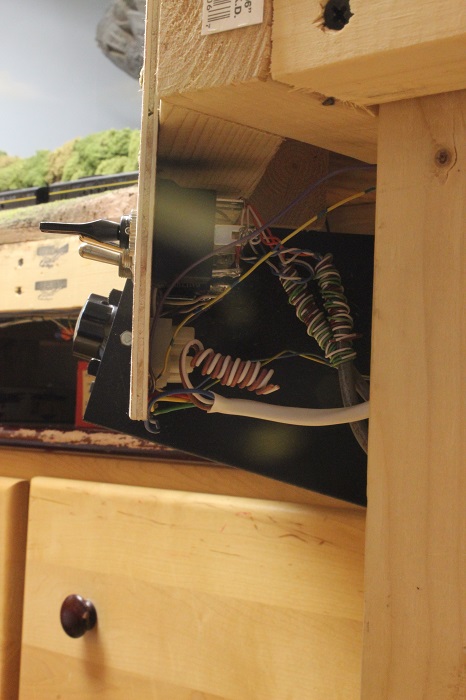
The coils that activate the relays are powered by the transformer to the left. It's secondary side is 12 volt AC. I installed a bridge rectifier under it to convert the output to DC.
In Easton two wires are run to the switch. One comes from the relays and the other go's to the other switch in Bath.
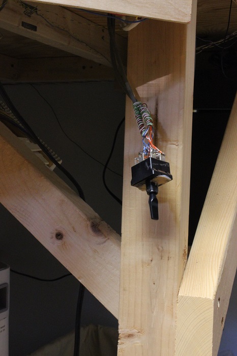
It is now back in it's original position.
I did make a quick video to show the relays operation.
![[Image: th_005-1.jpg]](http://i840.photobucket.com/albums/zz328/gronku2/the%20gauge/th_005-1.jpg) ![[Image: th_005-1.jpg]](http://i840.photobucket.com/albums/zz328/gronku2/the%20gauge/th_005-1.jpg)
For some reason the video posts twice I tried a few times to fix it but, no good. So watch it twice it you like  .
My other car is a locomotive, ARHS restoration crew
Posts: 2,724
Threads: 160
Joined: Dec 2008
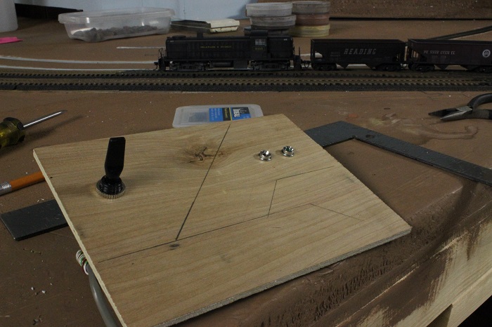
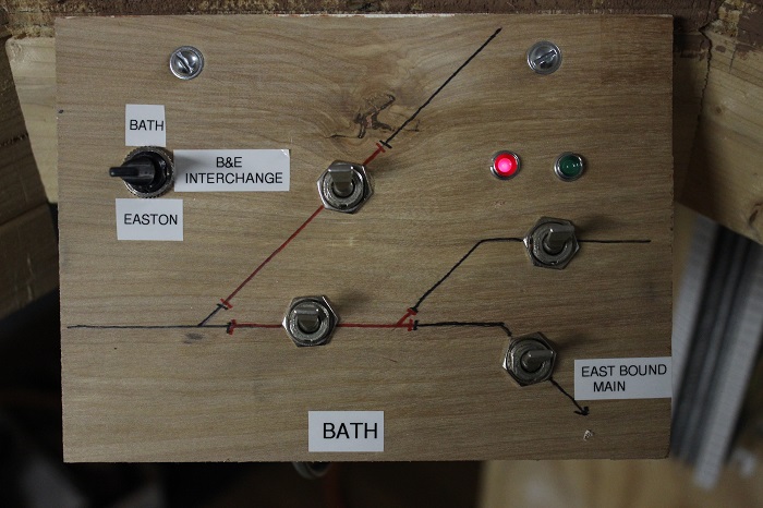
I started working on the control panel for bath, It's just like all the others I have done.. A thin scrap of plywood with a few switches installed in it, and a copy of the track plan drawn on it. I was lucky enough to catch a D&H train heading west with some empty coal hoppers in tow.
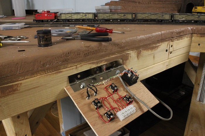
By the time I got the switches installed the cabin was just going past. You'll notice that I changed my mind and decided not use dwarf signals for the indicators. Now I've relocated them to the panel.
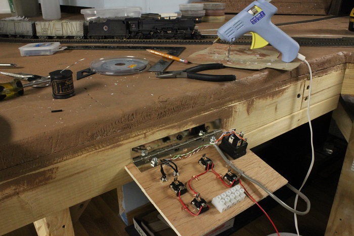
What I normally use to mount the panels is a piano hinge on the back of the panel. That will mount to the bench work. This allows me access to the switches for maintained by just lifting it up. Here I have mounted it upside down to make it easier to work on.
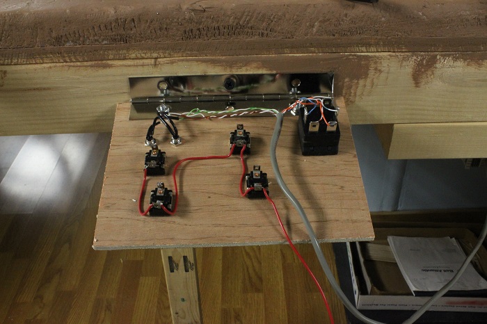
A little more work done here,, I also like to use a hot glue gun to secure the wire to the back of the panel. OOOO!!! and look,,, The LNE has got a cement train headed for Jersey with a L-1 on the point.
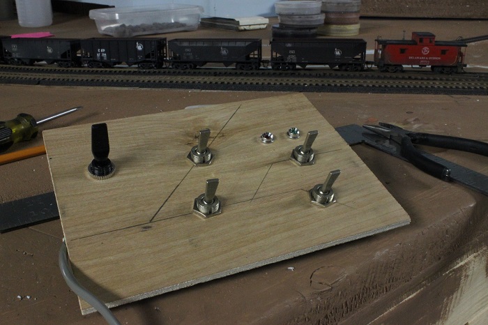
By the time the train had passed I managed to complete the wiring of the panel. I also installed a terminal strip at the bottom of the panel where the wires will connect to the rest of the layout.
My other car is a locomotive, ARHS restoration crew
Posts: 2,724
Threads: 160
Joined: Dec 2008
With the panel all finished, it has now been permanently mounted to the layout. In this shot you have the interchange switch on the left,, up for the cab in Bath to have control and down the cab in Easton. The red indicator means that this panel has been cut out and the Easton cab has control. With the green led lit, the Bath local cab has the train.
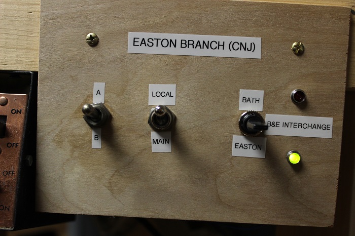
The panel in Easton operates the same way.. It shows that the Easton cab has control. The switch in the middle selects the local or main throttles, the one on the left selects either the A or B main cab.
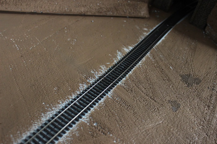
Just past the tunnel on the Bath side I have cut two gaps in the rails. This will allow the two local cabs (Easton and Bath) to be used at the same time by two different operators without the fear of causing a short.
My other car is a locomotive, ARHS restoration crew
Posts: 2,724
Threads: 160
Joined: Dec 2008
With the control panels in and the relays working It's now time to connect the west end of the Easton branch to the SH&D main in Bath.. So let's lay some track  ..
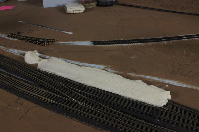
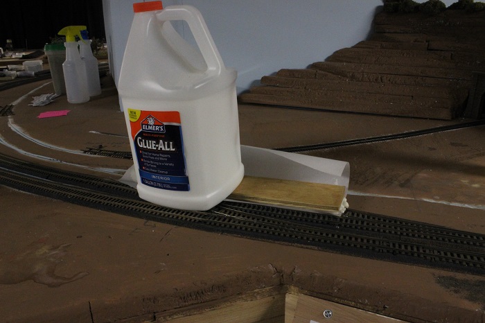
All of the new trackage will be owned by the Bangor & Easton Electric Railway. It's a fully owned subsidiary of the my freelanced SH&D (Anna Lines). I will not be installing any trolley lines, that would require me to finish all the scenery on the back side of the tracks in Bath. That is not in the scope of work for this project. In order to connect the B&E to the main I need to make a transition in height from the mains that are glued down to some Woodland Scenics foam roadbed to the B&E that is mounted directly to the layouts foam scenery base. I used a method that was taught to me by Garry (JGL Fan) . I applied some spray foam directly to the layout base where the roadbed ended, covered it with some parchment paper, waxed paper works also. I placed a scrap of wood over that and applied some weight to it.
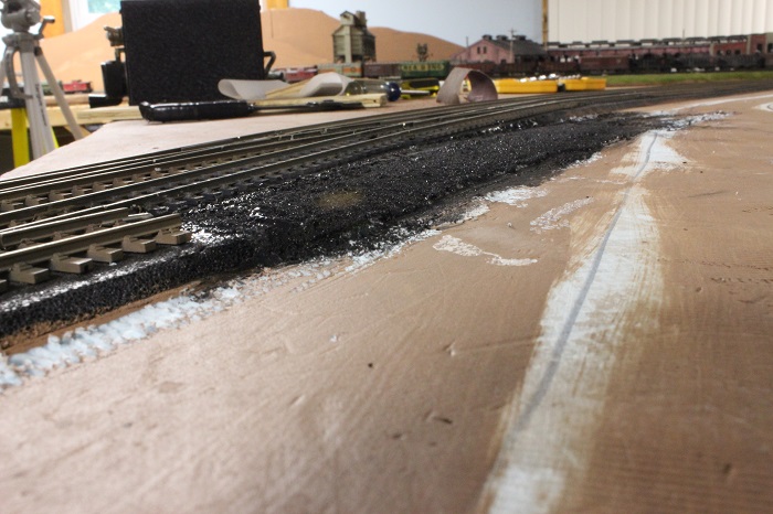
When it's dry everything just lifts right off.
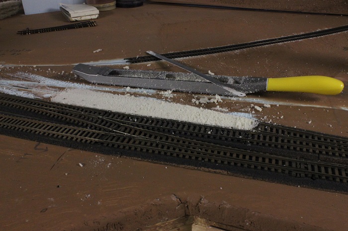
I use a rasp and hacksaw blade to shape and couture the dry foam into something that looks like roadbed.
When I'm happy with the shape I paint it black with some basic craft paint.
This shot shows the transition all shaped and painted.
My other car is a locomotive, ARHS restoration crew
Posts: 2,724
Threads: 160
Joined: Dec 2008
I built three #4 switches to use for the B&E during the week. I like the Fast Tracks gigs for hand laid switches. I'm not going to go into detail on this step there are a few demo's on YouTube on this subject. I will talk about how I control the turnouts. My method is to use a DPDT micro slide switch from All Electronics, part # ssw-45. It not only sets the polarity of the frog, but also holds the switch points in place. I have installed them on all of my hand laid switches without any problems so far.
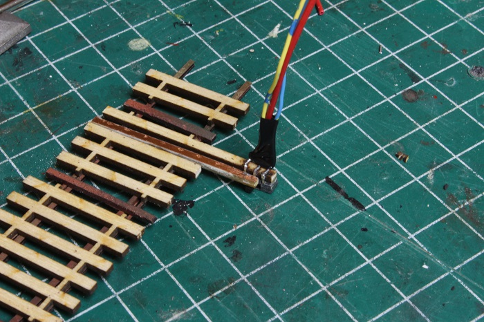
In this pic
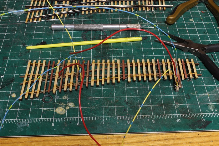
I have color coded the feeders to the rail and slide switch that has been glued to a longer tie with some CA type glue. On my layout the Yellow wire is the common rail and the blue will go to the switches on the control board for the block wiring. The red wire connects the center tap (common) on the slide switch to the frog. The slide switch has a pin through it that connects it to the through bar on the turnout. So when switch is set for either path the slide switch moves with it, holding the points in place, and the contacts send the correct power (+ or -) to the frog through the red wire. I will drill a set of small holes in the roadbed to the underside of the layout where all the wire will be spliced.
Here is a close up of the slide switch. The solder contacts on the switch are also peened over the tie to help hold it in place.
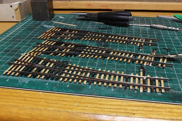
now they need to be painted and they will be ready to be installed.
My other car is a locomotive, ARHS restoration crew
Posts: 2,724
Threads: 160
Joined: Dec 2008
The rest of the B&E trackage is all in so Easton is now connected to the rest of the layout in Bath.
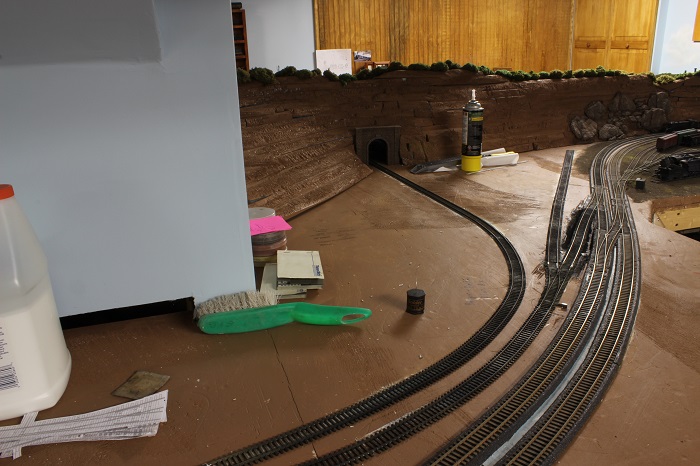
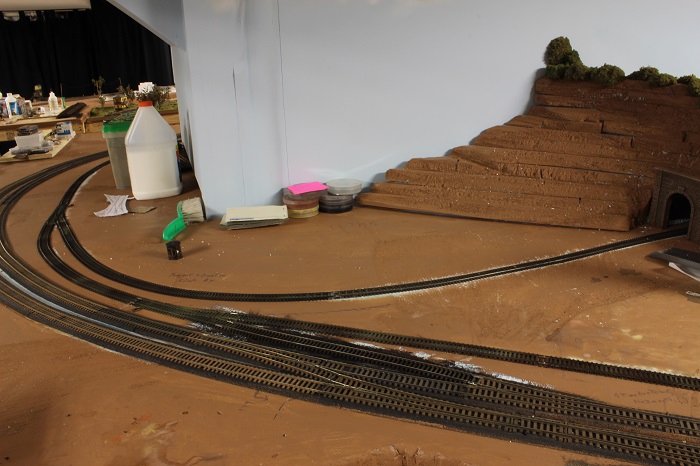
My other car is a locomotive, ARHS restoration crew
Posts: 3,755
Threads: 44
Joined: Dec 2008
Quite the project ! Looks like you are making good time with the progress so far. 
Mike
Sent from my pocket calculator using two tin cans and a string
Posts: 2,724
Threads: 160
Joined: Dec 2008
For the next part of this challenge I have a switch that needs some attention.
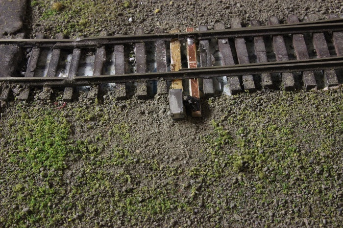
It sits on what will become part of my Gern plant at the western edge of Easton. You'll notice on the side of the layout near the switch it's labeled Nazareth, That was the original track plan, It's all different now. The switch is so close to the edge of the layout that the bench work interferes with switch machine that I was trying to mount under the layout. At that time I was using a version of a switch machine that Garry S. had come up with. Lately I have been using the type that I have talked about earlier. I just never got around to it.
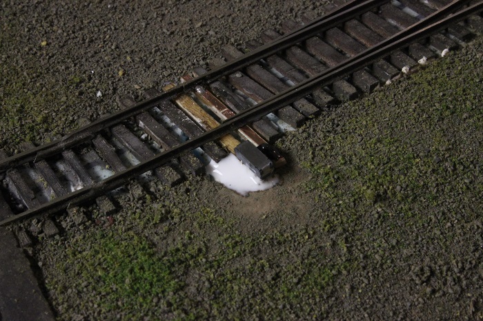
I first removed the through bar and the first tie before it, and cut a new PC board tie to fit it the location of the old through bar. This was soldered to only one of the switch points. I also filled in the hole in the foam with a piece of a paper towel.
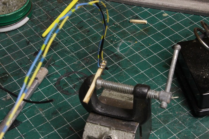
I took a new wooden tie, attached a slide switch to it, and soldered the leads to it.
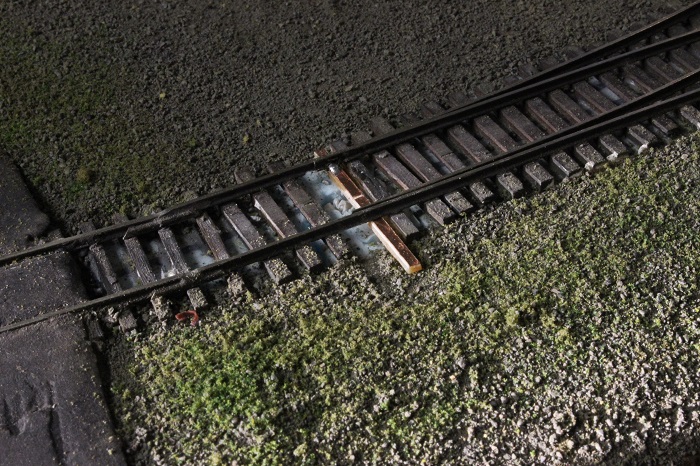
I drilled a new hole on the table and fished my wires in I used some white glue to secure the tie/switch assembly in place.
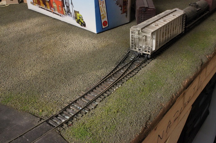
I covered the aria with some dirt to blend it in and soldered the other switch point in place with the slide switch in the correct position. This gives me the proper gauge and clearance on the switch points.
My other car is a locomotive, ARHS restoration crew
Posts: 2,724
Threads: 160
Joined: Dec 2008

I then painted the ties and solder to match the rest of the switch. It's still wet and shinny in this pic.
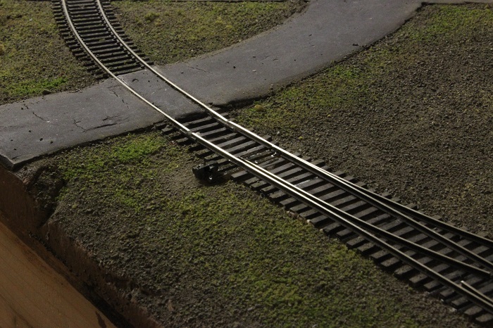
This shot is of the underside of the layout, you can see the clearance problem. I also finished the wiring so that the frog will be live.
My other car is a locomotive, ARHS restoration crew
Posts: 2,724
Threads: 160
Joined: Dec 2008
With the bad switch at the west end of Easton now working correctly, it's now time to turn my attention to the two switches at the other end of town. These two switches were already wired from when I installed them some time ago. They are just out of reach, and need a way to operate them from the layout edge. So I did some research and decided to go with the Tortoise machines. They will allow me to do all this from one DPDT switch each. I've never used them before so it will be a learning experience for me.
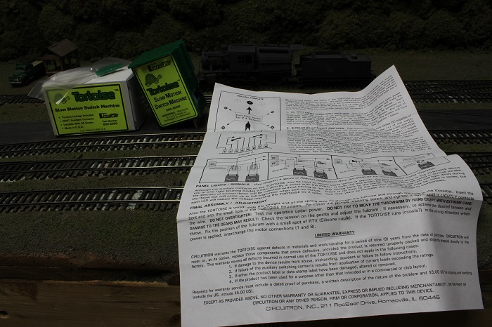
I ordered a set of them from The Black hand over in Brooklyn NYC.
My other car is a locomotive, ARHS restoration crew
Posts: 2,724
Threads: 160
Joined: Dec 2008
I did a bunch of work in Easton over the last week...
I soldered a set of leads to the switch-machines, making sure that I soldered all the same color wires to the same pins, and marked the leads as #1 and #2.. This way I can do the rest of the connections from the edge of the layout, spending less time under the layout is always good.

They were mounted in place under the turnouts that they will control. I already had the holes drilled in the bench work from when the track team came through town, so that speed things along. I did have to use a new spring wire to reach the points of the switch, the stock one was too short.

The Tortoise switch-machines have two sets of dry contacts that I put to good use. The first set was used to power the frogs and the other was used to to power a set of indicator lights that I added the control panel in Easton.


I used the same power supply to power my led indicator lights as I did earlier, The motor drive on the Tortoise's gets there power from the same supply as the coils on the relays.

My other car is a locomotive, ARHS restoration crew
Posts: 2,724
Threads: 160
Joined: Dec 2008
My next neglected project in Easton was to ballast the track work. Most of it looks like this....

That will not do.
I mixed up a batch of ballast from some tile grout, coal dust, dirt, and ground foam.

It was applied just the same as anyone else would.

I wanted to mimic the type of ballast that the CNJ used on it's L&S division ( the trackage in Pennsylvania). Most of the ballast there in sparse and uneven, so that was the look that I was going for.
My other car is a locomotive, ARHS restoration crew
Posts: 2,724
Threads: 160
Joined: Dec 2008
I did get to finish up all the ballast yesterday so here are a few pics.


Another thing that I managed to get to was was to cover the underside of the layout with some cloth. I picked up a set of black curtains that were large enough to cover the unsightly under side of Easton. I had to cut some slits into the cloth for the wires that go to the control panels to clear, And a hole for the local cab to pass through. I did realize that my sewing skills are somewhat lacking at this point, but I did get the job done.


Now I can start working on a fascia board to finish up the trim work on the edge of the layout.
My other car is a locomotive, ARHS restoration crew
|


 Also all the track leading up to that switch is dead. At the other (west) end of town the track ties into another railroad. The Bangor & Easton is the section of that turns off into the tunnel portal.( shown here )
 It is supposed to connect back to SH&D rails on the other side of the mountain in Bath. But some one has stolen the track
  hock: .


 hock: .


![[Image: th_005-1.jpg]](http://i840.photobucket.com/albums/zz328/gronku2/the%20gauge/th_005-1.jpg)
 .
.
