Posts: 305
Threads: 13
Joined: Sep 2013
A thread in another forum trying to identify this car caught my interest and I filed away the following for a “to do” project.
A link to the original photo.
<!-- m --><a class="postlink" href="https://www.flickr.com/photos/losalamosnatlab/7597514026">https://www.flickr.com/photos/losalamos ... 7597514026</a><!-- m -->
The direct link to the answer....
<!-- m --><a class="postlink" href="http://southern.railfan.net/flat/cars/cisx/cisx500.html">http://southern.railfan.net/flat/cars/cisx/cisx500.html</a><!-- m -->
......and following the crumbs.......
<!-- m --><a class="postlink" href="http://www.rr-fallenflags.org/misc-frt/cisx500alb.jpg">http://www.rr-fallenflags.org/misc-frt/cisx500alb.jpg</a><!-- m -->
The link to Tom Daspits very informative site which includes the section on Large Flat Cars.
<!-- m --><a class="postlink" href="http://www.garlic.com/~tomd/">http://www.garlic.com/~tomd/</a><!-- m -->
So with the above sources along with the help of another modeller who came up with further information from the January 1942 O.R.E.R, I decided the following was enough to try a build.
“Breaking all records for size, this monster well car 90 ft long over the coupler pulling faces, has a load capacity of over 250 tons. Designed for use in carrying ingot molds between two Carnegie-Illinois plants, it is fitted for regular interchange movements. To carry this enormous load safely and economically, the two six wheeled trucks under each of the auxiliary bodies are provided with U.S.S Wrought Steel Wheels, 36 in. in diameter.
Pertinent Facts. Total weight of the car is 313,900 lb, of which 107,920 lb is in the four trucks, 49,000 lbs in the two auxiliary bodies, and 156,980 lbs in the well body proper. Payload capacity, at a rail load limit of 70,000 lbs, per axle, is 526,100 lbs. The total rail load is 840,000 lbs.
The well-platform is made up of seven long H-Beams, jigs assembled and are welded longitudinally. Each H-Beam in turn is made up in 5 sections- the central platform piece, two reverse curve transition pieces and two end pieces which terminate at the main bolster......”
Outside length 87'6"
Width @ eaves or top of sides or platform 9'8"
Extreme width 9'8"
Capacity 526100 lb.
Flat car, Depressed, steel, Note A: Car No. 500: height from rail to top of depressed platform 2 ft. 8-3/4 inch, to top of car body 6 ft. 9-1/2 inches; length of depressed center 18 .”
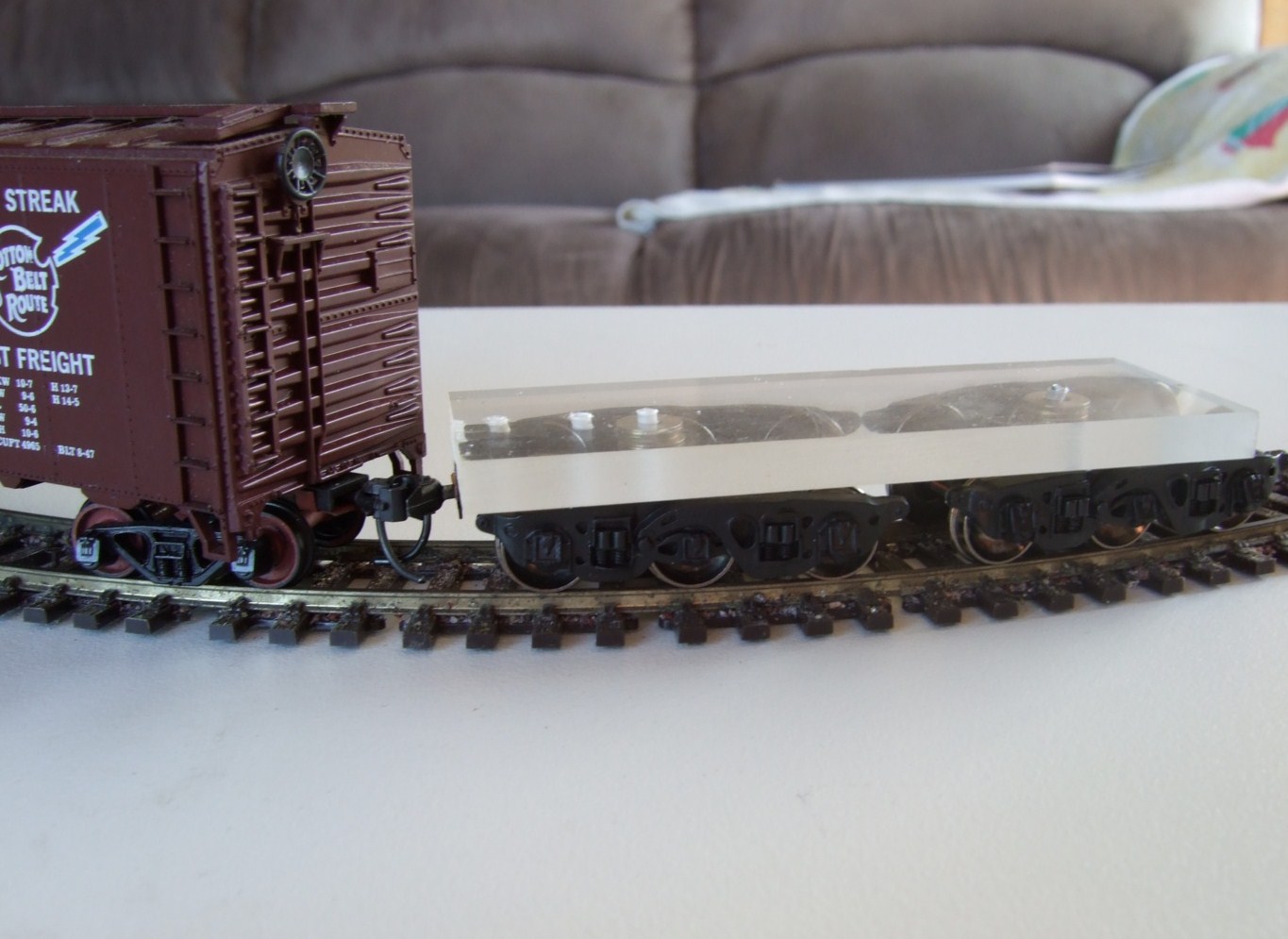
Armed with the above information I first sourced some affordable and more importantly available Buckeye trucks, Athearn ATH90407 and quickly knocked up a test car see if my requirements for overall heights, correct coupler height, and ability to run through my 15 inch radius test track.
As the trucks ticked all the boxes I then proceeded with an accurate (?) HO scale drawing.

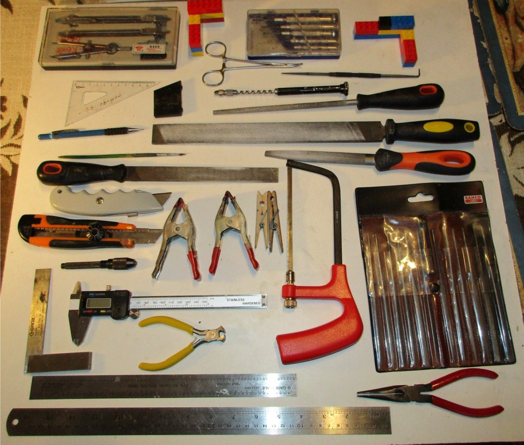
One of my self imposed limits was that I used only hand tools that I would expect most modellers to have.
Thanks for looking, Cheers, the Bear. 
"One difference between pessimists and optimists is that while pessimists are more often right, optimists have far more fun."
Posts: 305
Threads: 13
Joined: Sep 2013
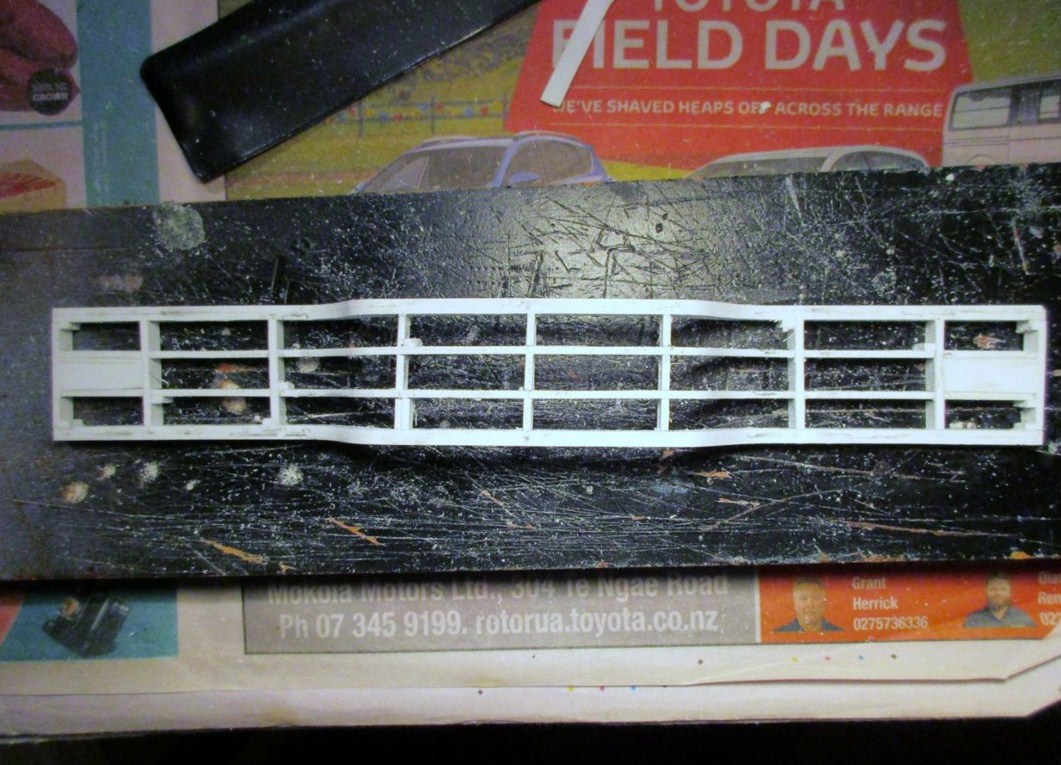
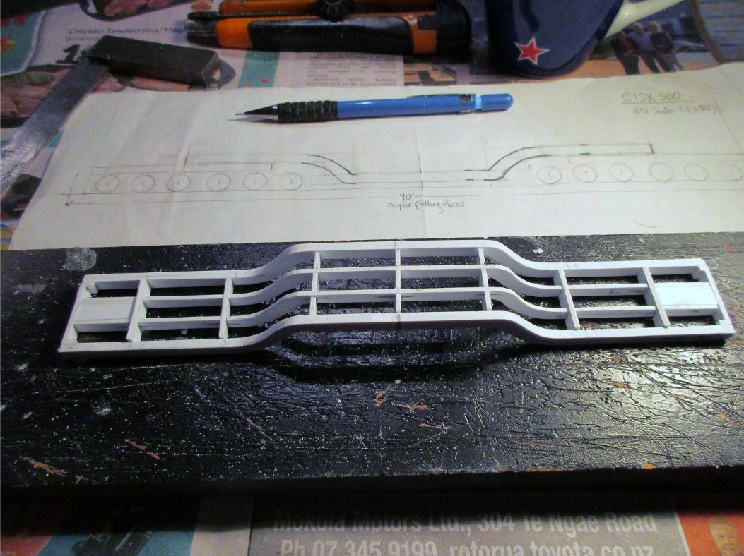
The six longitudinal beams were cut from .060” styrene sheet, the two outer beams being laminated together. The ribs were also cut from the same material and then assembled using MEK as the bonding agent. The outside of the frame is square but some of the ribs are less than perfect, Ok if they’re to be hidden but still it is not best practice,  (I need a lot more).
I dithered on the thickness of the deck, knowing full well the thicker I made it the more work required, but .030” styrene looked about right.
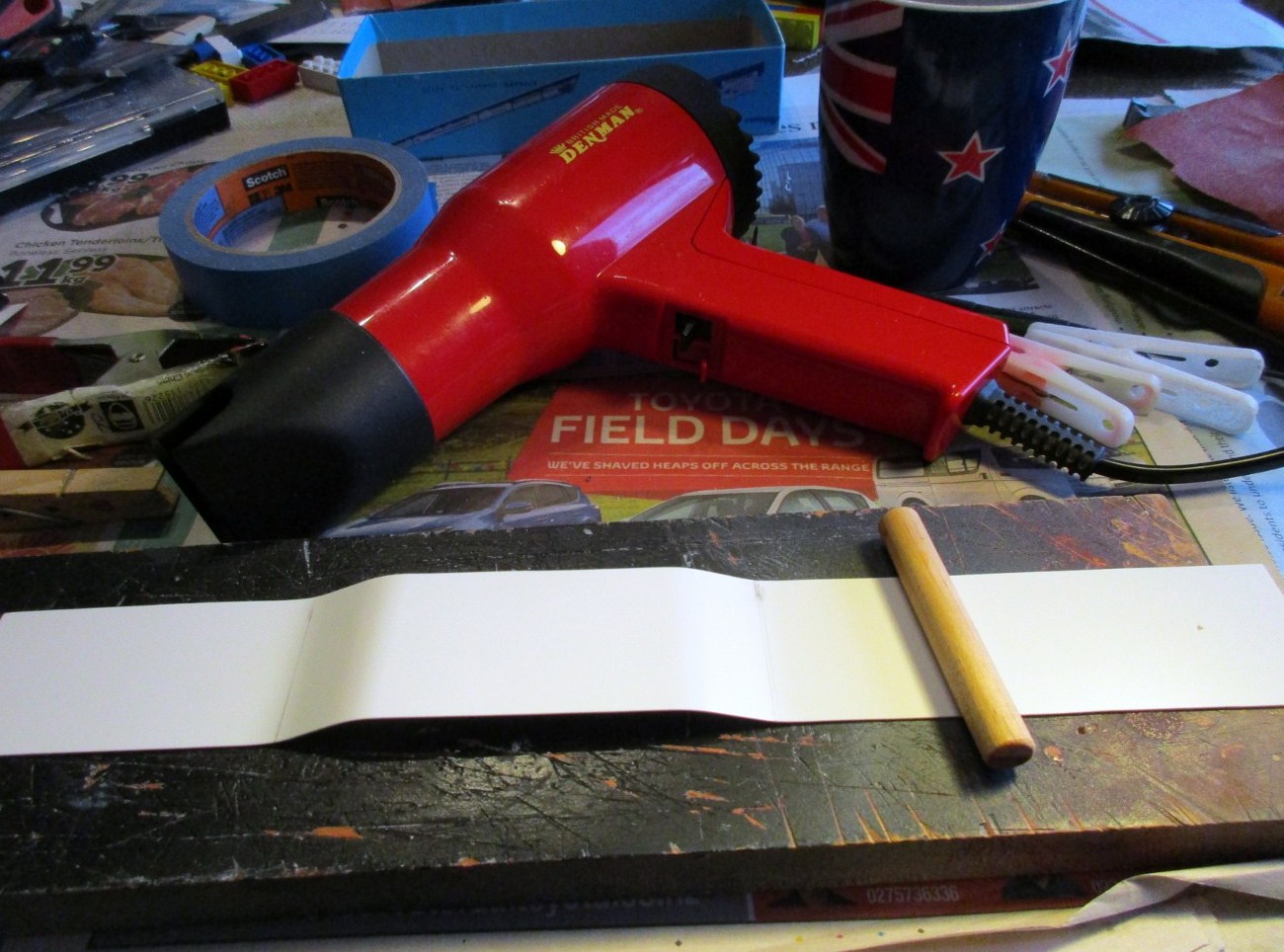
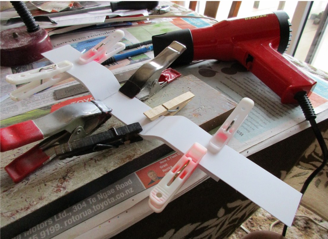
As you see in this photo, my grand aim of building this with common hand tools was shot down in flames as I bet Her-in-doors hair dryer is not part of a modellers’ everyday tool box!! :oops:
With the certain knowledge that I could end up with a molten pile of styrene and with more patience than I knew I had, and with the aid of a piece of dowel and judicious use of the hair dyer I ended up with the preformed deck, and, later, a bottom.
Thanks for still looking, Cheers, the Bear. 
"One difference between pessimists and optimists is that while pessimists are more often right, optimists have far more fun."
Posts: 612
Threads: 10
Joined: Feb 2011
Certainly an interesting prototype Bear, especially when you see the photo of the officials standing next to it to give some perspective.
Carry on.
Mark
Fake It till you Make It, then Fake It some More
Posts: 990
Threads: 47
Joined: Jan 2009
Great start of your model description, Bear!
I'm very interested the progress of your model! What do you plan to use as load?
Cheers, Bernd
Please visit also my website www.us-modelsof1900.de.
You can read some more about my model projects and interests in my chronicle of facebook.
Posts: 305
Threads: 13
Joined: Sep 2013
Mr Fixit Wrote:Carry on.
Carrying on.... 
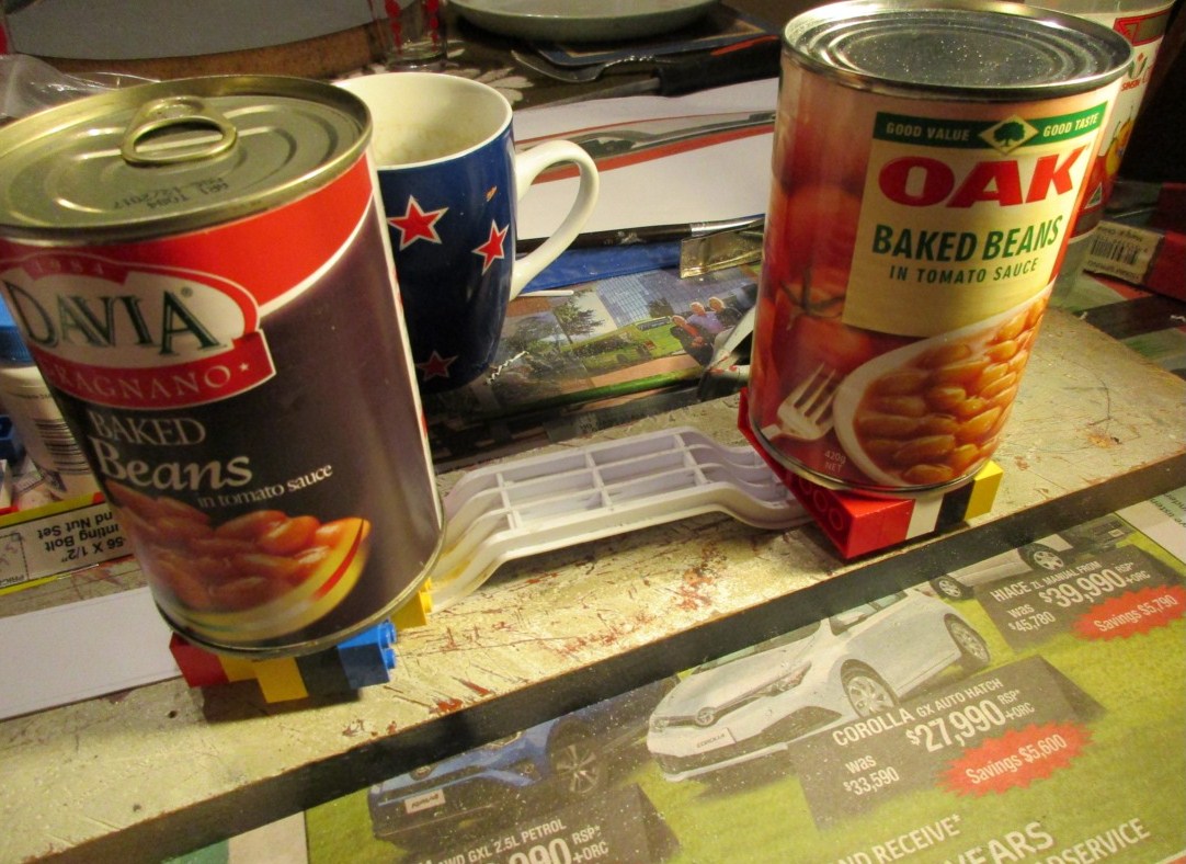
While I was happy with the preformed deck, it wasn’t 100% and though it needed very little persuasion to fit the frame, I was still conscious that at the worst I could end up with a styrene pretzel or, and still not that good, the decks out of parallel. So with various clamps, a flat surface and weights, I slowly continued bonding the deck to the frame a little a bit at a time.
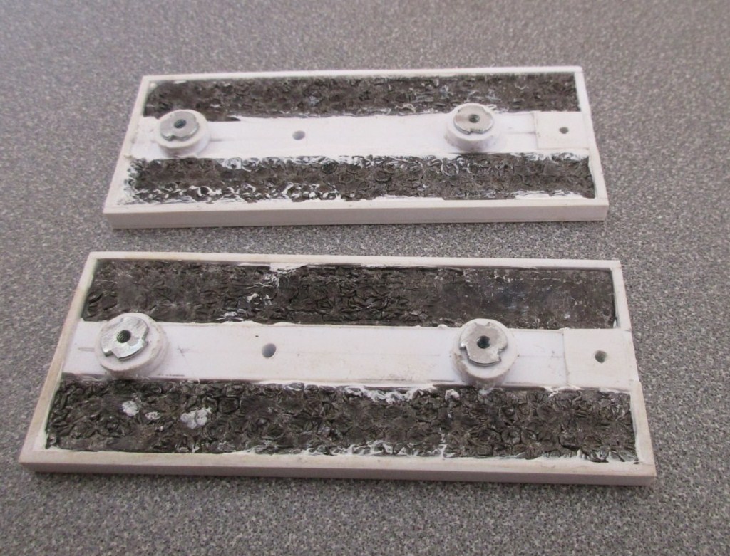
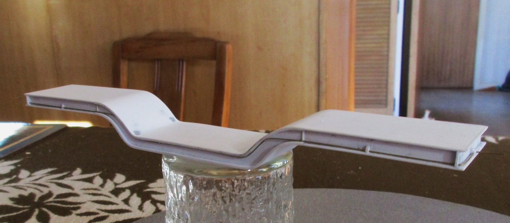
I then did the same with the bottom, and while not that clear in the photo added .010” strips to the top and bottom sides of the centre part of the well deck, added the brake line, and reasonably satisfied put the well deck to one side.
Cutting out the parts required from .060” styrene for the sides and ends and .040” for the deck, I assembled the auxiliary cars which you will see are completely unprototypical but I wanted to be able cram in as much weight as possible, which I did using the doctorwayne method. The car currently weighs one ounce more than the NMRA recommended standard.
modelsof1900 Wrote:I'm very interested the progress of your model! What do you plan to use as load?
Bernhard, building a load wasn’t a priority as I wanted to see if the car would run properly provided I could actually build it!
“Jumping the gun” as I now know it runs well, I’ve decided to build at least two and probably three loads though none will be up to the standard as seen here  ........
<!-- l --><a class="postlink-local" href="http://bigbluetrains.com/forum/viewtopic.php?f=22&t=8257">viewtopic.php?f=22&t=8257</a><!-- l -->
One has to be one of the Carnegie Illinois Steel ingot molds and I’m mulling over some other ideas.
Thanks for looking,
Cheers, the Bear. 
"One difference between pessimists and optimists is that while pessimists are more often right, optimists have far more fun."
Posts: 1,682
Threads: 101
Joined: Dec 2011
Very interesting project. Are you using small T-nuts to bolt the trucks?
Could it have been a good idea to put some weight into the central depressed structure?
Matt
Posts: 5,859
Threads: 175
Joined: Dec 2008
JaBear Wrote:......One has to be one of the Carnegie Illinois Steel ingot molds....
I'm curious as to the size of those moulds. Ingot moulds were usually transported in gondolas - one or two, depending on the size and weight, at each end of the car.
At the steel plant where I worked, the largest ingots were roughly 25 tons, and the mould (and stool) for them would have been about the same weight. Not really too taxing for a 70 ton gondola.
Regardless of that, I'm enjoying watching this project as it develops.   
Wayne
Posts: 305
Threads: 13
Joined: Sep 2013
sailormatlac Wrote:Could it have been a good idea to put some weight into the central depressed structure?
Gidday Mark,( My Apologies Matt  ) like most of us I don’t build things to fail but I always had concerns over how well the car would articulate over curves. So I opted to make the well platform light but strong knowing that I did have the option to add weight by adding a load.
sailormatlac Wrote:Are you using small T-nuts to bolt the trucks?
My use of T nuts is explained in this instalment.
Using T nuts is probably overkill on my behalf but in my part of the woods the ability to purchase 2-56 screws without nuts of some type is nearly impossible, actually purchasing 2-56 screws can be slightly problematic at the best of times so I buy what’s available as long as they’re not at a gold plated price, thank goodness for the RC aeroplane builders. Coming from the waste not want not camp, and as I am concerned of being heavy handed (pawed) and stripping the threads out of the styrene, I put these nuts to use.

One of the spotting features of this car is the brake cylinders mounted on the buckeye trucks and as I had nothing suitable, and after several false starts and failures came up with this. Now I just have to complete the other seven.

doctorwayne Wrote:I'm curious as to the size of those moulds.
Gidday Wayne, my knowledge of the steel industry is rudimentary at the best but as this car was designed to transport ingot moulds between two Carnegie-Illinois plants I presume that it is an ingot mould that’s depicted in this photo, from Tom Daspits site.

There’s another photo at this link, though I’m none the wiser as to why it needs to be so big....
<!-- m --><a class="postlink" href="http://gathpast.tripod.com/tour1.html">http://gathpast.tripod.com/tour1.html</a><!-- m -->
And while I first posted this in the latest WPF here’s links to the car on its test runs.
<!-- m --><a class="postlink" href="https://youtu.be/4Af9AUmDPDU">https://youtu.be/4Af9AUmDPDU</a><!-- m -->
<!-- m --><a class="postlink" href="https://youtu.be/ITEF-JhVR2w">https://youtu.be/ITEF-JhVR2w</a><!-- m -->
Thanks for the kind comments and for looking,
Cheers, the Bear. 
"One difference between pessimists and optimists is that while pessimists are more often right, optimists have far more fun."
Posts: 5,859
Threads: 175
Joined: Dec 2008
Thanks for posting that photo, Bear. That certainly is a large ingot mould, but a very rough calculation puts its weight at about only 150 tons. Clearly, the car's low deck is as important as its carrying capacity in this example.
That mould appears to be for a big-end-up ingot, which would be removed from the mould rather than having the mould stripped from it. Such moulds were generally used for fully-killed steel, usually made with very specific alloys for specialty uses. Re-heating such ingots for rolling required very specific procedures, and, depending on the temperature at which that ingot was placed in a soaking pit, could take days to accomplish.
It's difficult for me to imagine its end-use, and the machinery and procedures to get it to that stage.
Wayne
Posts: 612
Threads: 10
Joined: Feb 2011
Page 3 of that Tripod link indicates that the ingots are to be used for amour plate for tanks and ships.
Either way we are talking about very large lumps of very hot steel. 
Mark
Fake It till you Make It, then Fake It some More
Posts: 305
Threads: 13
Joined: Sep 2013
Gidday Wayne as I was only looking for information on the car, and also because ignorance is bliss, I didn’t take much notice of the other pages in this link. (I presume that the links work for others)
<!-- m --><a class="postlink" href="http://gathpast.tripod.com/tour1.html">http://gathpast.tripod.com/tour1.html</a><!-- m -->
Now there is I believe a discrepancy in some of the captions at the very least, because they refer to the photo of the car as taken in the late thirties, whereas CISX 500 has the build date of 10 41.
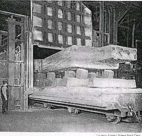
However this photo, and I’m not sure how it will reproduce shows, I presume, one of the ingots from G11 mould, (there’s a photo showing an identical G13 mould) starting a process. The bloke standing at the left gives scale.

The caption reads, This picture shows a large ingot which is about to be reheated for strength. This steel is about to be turned into armour for use in the Second World War. The idea is to take the steel with the lowest possible amount of impurities, and reheat it in manners which strengthen the metal. This ingot was used in the production of tanks or ships. The finished metal would be rolled into armour.
Polished and etched section of Gathmann type ingot of Molybdenum Chrome Low Carbon Steel.
As I have stated I wouldn’t know what standard practise was in the steel industry if it bit me on the leg, but hopefully this makes sense to you.
Cheers, the Bear. 
Edit, I see Marks posted while I've been writing.
"One difference between pessimists and optimists is that while pessimists are more often right, optimists have far more fun."
Posts: 5,859
Threads: 175
Joined: Dec 2008
Yes, it does make sense to some degree, but the size of the ingot is still puzzling me. The steel company at which I worked also produced armour plate and the ingots were similar in shape, but less than 30 tons. I'd estimate that we produced at least two dozen grades of steel suitable for use as armour plate, the particular grade dependent upon the particular use and the particular customer - the U.S. military was the biggest customer of those grades from our company. This type of steel, in ingot or slab form at least, is very sensitive to sudden changes in temperature. For that reason, there were special procedures (time constraints) for stripping the ingots from their moulds and for re-heating ingots for rolling (soaking pit charging temperatures and graduated temperature increases dependent on the temperature of the steel at charging). Rolling temperature, as I recall, was about 2400°F, which is 50°-100°F hotter than most grades. Much of what we rolled was not put though the hot scarfer (a machine with adjustable torch heads through which a slab would pass, the torches playing on the entire circumference of the slab as it moved at slow speed along the roller line. These torches burned natural gas with oxygen, and were used to remove surface imperfections). Most of these ingots were rolled to thicknesses beyond the capacity of the crop shear, which could handle slabs up to 500 sq. in. in cross-section, so most of these ingots left our mill as one-piece "blooms" (semi-finished slabs).
Once rolled, the blooms were stacked, then placed under steel covers lined with firebricks. When they reached a specific temperature, they were shipped to the plate mill for re-heating and rolling into plate, again using procedures similar to those outlined for ingots. The chemical make-up of the steel, coupled with the heating and cooling cycles, and the rolling operations all contributed to the durability of the resultant plate.
Wayne
Posts: 305
Threads: 13
Joined: Sep 2013
With my new found Knowledge (???)  garnered from your explanation Wayne, I wonder if the large ingot size was one of those “good ideas”, (for example “the bigger the better syndrome”), that was taken several steps too far, hence it not becoming a general practice?
Cheers, the Bear. 
"One difference between pessimists and optimists is that while pessimists are more often right, optimists have far more fun."
Posts: 612
Threads: 10
Joined: Feb 2011
I am thinking that with a build date of October 1941, the car was built to handle larger ingots that would be needed to handle the vast amounts of armour plate required during a World War. At the time of building the car, the US was well along the road to becoming a war economy as it was already "The Arsenal Of Democracy" helping to to supply those already fighting the Axis forces with weapons and munitions, tanks, aircraft, trucks, and everything else required in time of war. Indeed at this time the US was in the twilight of is last days of "peace", gearing up and manning up for a war that was spreading around the world, and that would spectacularly burst forth on Sunday, December 7, 1941.
As I understand it, a larger ingot would retain it's heat longer following its pouring and then during transit between one plant and the next and, so reduce the amount of "soaking" time and energy required to bring it back up to heat prior to rolling at the next plant.
Mark
Fake It till you Make It, then Fake It some More
Posts: 305
Threads: 13
Joined: Sep 2013
Well I see it’s only taken me almost six months to almost finish this car. I say almost because it really deserves a load and a bit of light weathering but that will have to wait if I want to have any chance of completing my Duff challenge.


Thanks for looking.
Cheers, the Bear.
"One difference between pessimists and optimists is that while pessimists are more often right, optimists have far more fun."
|


 (I need a lot more).
 ........
 ) like most of us I don’t build things to fail but I always had concerns over how well the car would articulate over curves. So I opted to make the well platform light but strong knowing that I did have the option to add weight by adding a load.
 garnered from your explanation Wayne, I wonder if the large ingot size was one of those