01-26-2023, 08:04 PM
Part 2, Scene 3, Lights Please!
I'm a glutton for punishment. I get something in my head and I have to try it. Charlie's suggestion of drilling a hole in the light socket front and rear to accept the LED is a great one, but I wanted to try something different with this loco. I'm going to try building a light box for each of the LEDs. If the results aren't up to snuff, just like anything else on my layout, pull up the hook and start over.
Started building a box for the rear light and number boards last night with a sheet of sytrene, and it was surprisingly quick and easy. The EMD units have that classic prow shape on each end, so I cut a piece of styrene the width of the inside shell and then played around with some scissors to try to get that prow shape. I'd test fit, shave a little off (sandpaper came in handy) and test fit again. Finally arrived at the right shape, cut it to about an inch in length and then folded the back edge upward to form the box.
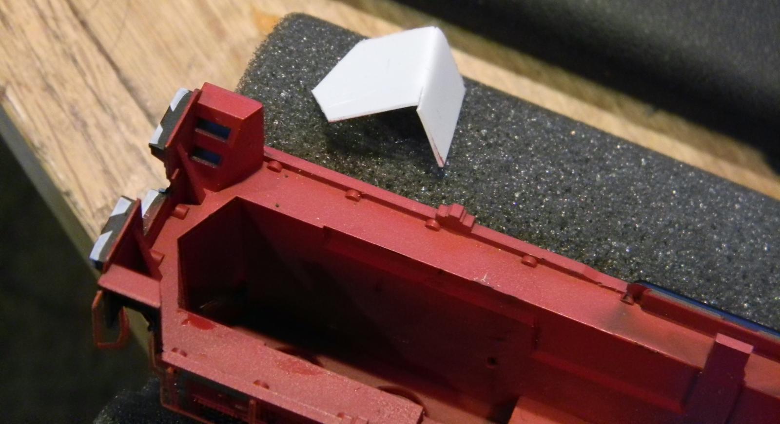
Drilled a hole in the back for my LED which had a nice friction fit. Pushed it into place at the deepest area of the back corner of the shell to test fit the final configuration.
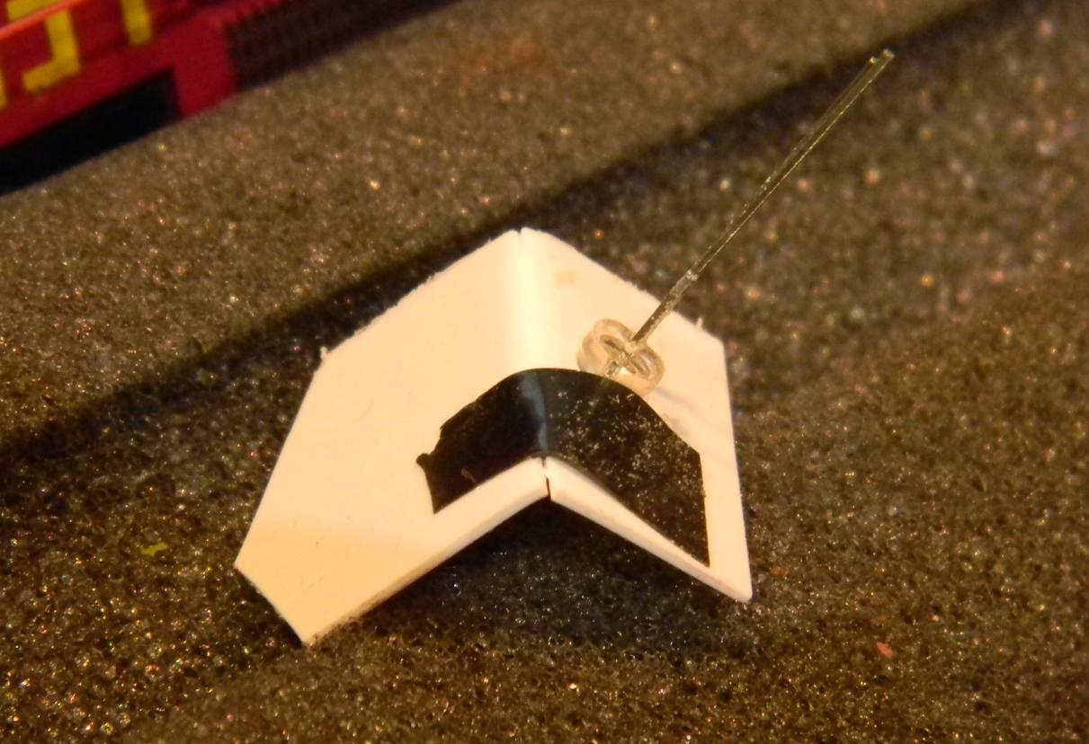
I thought the front light was going to be a lot more complicated, but I was again pleasantly surprised. Carefully disengaged the cab from the rest of the shell (removed the 4 handrails and gently pried the plastic keepers that hold the cab in place to the shell). The Athearn design has a single window glass assembly that wraps around the cab. Just above it is enough space to add a ceiling and there's enough room there to slide an LED in between the ceiling and the bulkhead. Cut out another piece of styrene to fit the dimensions of the cab,
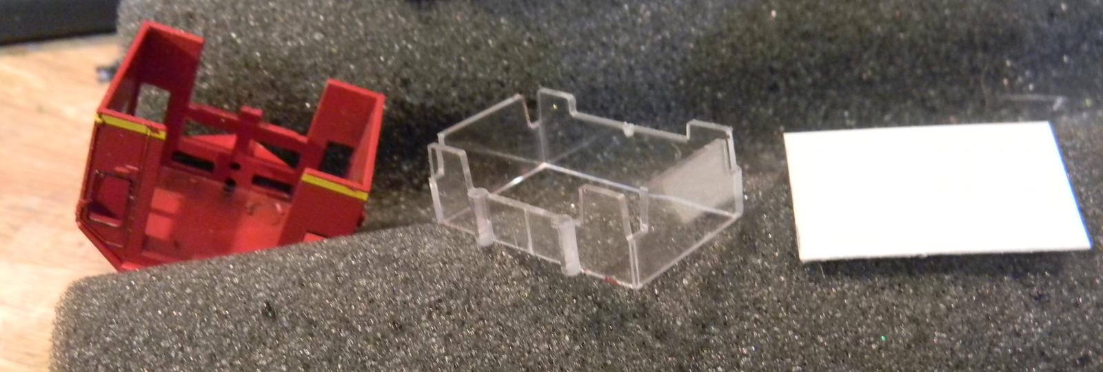
removed the window assembly, and pushed it into place. I did have to cut a bit off the sides to accommodate the roof corners, but after some trial and error, it fit quite nicely.
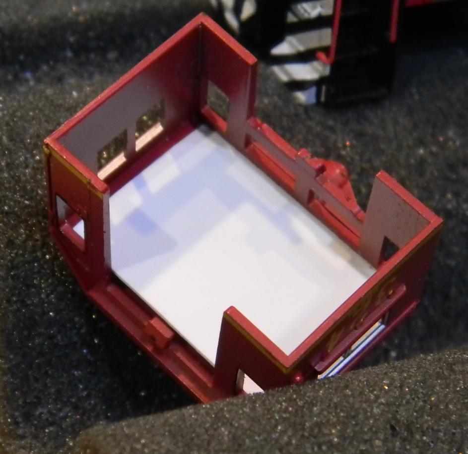
Checked the LED for fit, and with a little wiggle, we'll get 'er in even with the cab in place on the shell.
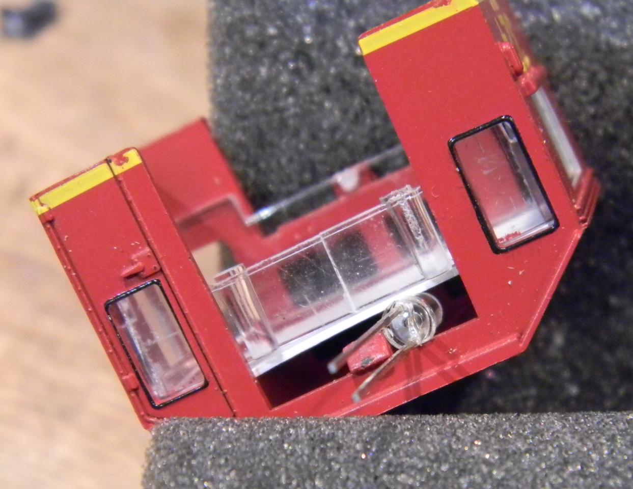
So, I now know where my LEDs will need to be and I can figure out how long the leads to each will need to be and I can start the soldering station up for the night. As Charlie pointed out earlier, the blue wire is actually the common POSITIVE for each of the lights, so I'll try to use that to my advantage. I'll cut the blue wire short, solder on the resistor, and then feed two new wires to the positive side of each LED. The positive side of the LED (for virgin LEDs right out of the bag) is the longer leg coming out of the plastic housing. It's also the "round" side of the LED bulb (the negative side has a flat spot on the side of it). I'll solder a wire to each one and run some heat shrink over the exposed joint and metal lead. I'll also do the same for that resistor - don't want any of those metal pieces touching any part of the chassis, which still provides a connection back to the left side of the track. Some pictures will follow tomorrow. Just discovered I don't have any small heat shrink to go over the leads on those LEDs, want to pick some up tomorrow.
Had another thought. I think I'll keep the cab off of the shell for a while, and I'll definitely keep the window assembly out until after I finish painting and weathering. Spraying Dullcote means unless you mask the windows, they'll end up foggy. While it's off I may also add the "7" the the Road number and I may explore revamping the number boards while it's easy to get at them.
I have a day off tomorrow and may have some time to work on some of this stuff in the daylight hours.
I'm a glutton for punishment. I get something in my head and I have to try it. Charlie's suggestion of drilling a hole in the light socket front and rear to accept the LED is a great one, but I wanted to try something different with this loco. I'm going to try building a light box for each of the LEDs. If the results aren't up to snuff, just like anything else on my layout, pull up the hook and start over.
Started building a box for the rear light and number boards last night with a sheet of sytrene, and it was surprisingly quick and easy. The EMD units have that classic prow shape on each end, so I cut a piece of styrene the width of the inside shell and then played around with some scissors to try to get that prow shape. I'd test fit, shave a little off (sandpaper came in handy) and test fit again. Finally arrived at the right shape, cut it to about an inch in length and then folded the back edge upward to form the box.
Drilled a hole in the back for my LED which had a nice friction fit. Pushed it into place at the deepest area of the back corner of the shell to test fit the final configuration.
I thought the front light was going to be a lot more complicated, but I was again pleasantly surprised. Carefully disengaged the cab from the rest of the shell (removed the 4 handrails and gently pried the plastic keepers that hold the cab in place to the shell). The Athearn design has a single window glass assembly that wraps around the cab. Just above it is enough space to add a ceiling and there's enough room there to slide an LED in between the ceiling and the bulkhead. Cut out another piece of styrene to fit the dimensions of the cab,
removed the window assembly, and pushed it into place. I did have to cut a bit off the sides to accommodate the roof corners, but after some trial and error, it fit quite nicely.
Checked the LED for fit, and with a little wiggle, we'll get 'er in even with the cab in place on the shell.
So, I now know where my LEDs will need to be and I can figure out how long the leads to each will need to be and I can start the soldering station up for the night. As Charlie pointed out earlier, the blue wire is actually the common POSITIVE for each of the lights, so I'll try to use that to my advantage. I'll cut the blue wire short, solder on the resistor, and then feed two new wires to the positive side of each LED. The positive side of the LED (for virgin LEDs right out of the bag) is the longer leg coming out of the plastic housing. It's also the "round" side of the LED bulb (the negative side has a flat spot on the side of it). I'll solder a wire to each one and run some heat shrink over the exposed joint and metal lead. I'll also do the same for that resistor - don't want any of those metal pieces touching any part of the chassis, which still provides a connection back to the left side of the track. Some pictures will follow tomorrow. Just discovered I don't have any small heat shrink to go over the leads on those LEDs, want to pick some up tomorrow.
Had another thought. I think I'll keep the cab off of the shell for a while, and I'll definitely keep the window assembly out until after I finish painting and weathering. Spraying Dullcote means unless you mask the windows, they'll end up foggy. While it's off I may also add the "7" the the Road number and I may explore revamping the number boards while it's easy to get at them.
I have a day off tomorrow and may have some time to work on some of this stuff in the daylight hours.
Check out my "Rainbows in the Gorge" website: http://morristhemoosetm.wixsite.com/rainbows


