Posts: 1,349
Threads: 148
Joined: Jan 2009
the simplest aliment is what i use for my three modules (there at the club so no pics

now) it to drill two holes in each end that a section of 3/4 or 1 inch pvc pipe that is a tap in fit while its assembled ,to disassemble just tap pipe out. works well if your not moving the section too often.
jim
Posts: 989
Threads: 55
Joined: Dec 2008
Wow!!! Great work - really great work. That roundhouse is terrific!
Mark
Citation Latitude Captain
--and--
Lt Colonel, USAF (Retired)
Posts: 496
Threads: 22
Joined: Dec 2008
Posts: 1,229
Threads: 23
Joined: Dec 2008
I've heard of building scenery before the track is laid, but usually at least the roadbed is in place!

That's gonna be a humdinger of a scene.
Oh, and nice VGN TrainMasters...although I think the sideframes were black...are you going to repaint the engines for your road or keep them as is?
Galen
I may not be a rivet counter, but I sure do like rivets!
Posts: 3,683
Threads: 118
Joined: Jan 2009
Impressive work beign done here! And I sure like Russ' idea of the hinges. Sounds darned simple and effective to me.
Three Foot Rule In Effect At All Times
Posts: 2,724
Threads: 160
Joined: Dec 2008
Thanks everyone. Ocalicreek They will get painted for the home road ,If any one has undecorated Athearn shells I am willing to trade them. I have the 2 VGN's and a N&W that will get painted for the Anna lines. Just sent me a PM. The 2 pieces of track that will be the PRR line were just put in place to check clearances as I was building the seen. They are not permanent. I have check to see if I could find any pics of the PRR's track age that ran along the Delaware so that I could give it some real Pennsy flavor.
My other car is a locomotive, ARHS restoration crew
Posts: 1,817
Threads: 27
Joined: Dec 2009
I don't remember ever seeing the tracks along the Delaware River in Easton; our drive to the Poconos up Rt. #611 in the 1950's in Dad's old '49 Chrysler coupe, with play pen and high chair and stuff carefully tied down on the roof rack kept us back from the river banks, but I do recall (I think it was) the LV and CNJ on both sides and the L&NE crossing on the High Line way above up in the Water Gap!
BTW, the Delaware River scene is coming along just "swimmingly", but I was wondering, is that an indication of the Delaware Canal that I see?
biL
Lehigh Susquehanna & Western
"America will never be destroyed from the outside. If we falter and lose our freedoms, it will be because we destroyed ourselves." ~~Abraham Lincoln
Posts: 2,724
Threads: 160
Joined: Dec 2008
No Bil. your just seeing the roadbed. I will be modeling part of the canal near the roundhouse in Riegelsville PA.
My other car is a locomotive, ARHS restoration crew
Posts: 446
Threads: 23
Joined: Mar 2009
Hi Steve ; I like the Plymouth 60 toner. I remember it well. When you repaint it will it be named Emma. POP
" It's a Heck of a Day " !!!!
Posts: 1,797
Threads: 81
Joined: Dec 2008
Wow, that lift bridge is going to be amazing! Just like the ones around the Niagara Region spanning the Welland Canal. Nice job on the rest of the layout too.

Posts: 2,724
Threads: 160
Joined: Dec 2008
Now I felt that I should get going on the bridge it's self.I started by drawing the towers out in full size on some foam board. Really paying attention to keeping all the joints at right angles. I checked and checked again to make sure I was happy with it before I started building anything. The foam board will act as a template, so it has to be correct.
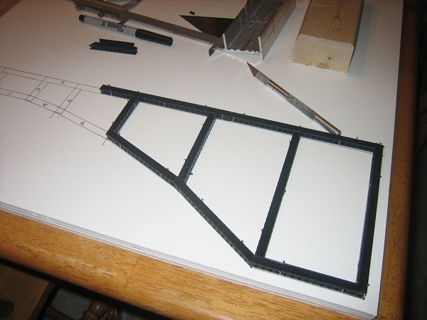
I Cut some Central Vally #1902-5 bridge girders as per my drawing and glued them in place. The next step was to hold them down using pins stuck into the foam board.
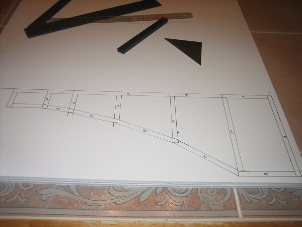
I will have to make 4 of them . They consist of Type A girders on the top and bottom with Type B-B as the remainder of the girders.
My other car is a locomotive, ARHS restoration crew
Posts: 2,724
Threads: 160
Joined: Dec 2008
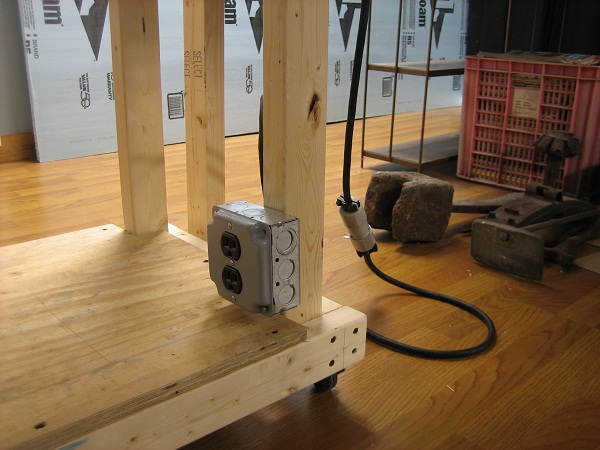
I gave the glue a chance to dry and installed a receptacle on the wheel out section. I'm not sure how I'm going to power the lifting section of the bridge yet. The 110 volt outlet will allow me a bunch of options. It's feed with a section of SO cord with a twist lock disconnect that will give me a safe way to remove the section with out turning off the power.I also made it long enough that I can move it around a little without unplugging it. The track power will be feed from a similar setup.

Then I sat back and ran some trains...

My other car is a locomotive, ARHS restoration crew
Posts: 3,683
Threads: 118
Joined: Jan 2009
That's going to be a nice bridge! And hope you had fun sitting back and watching the trains run.
Oh... Electricity is not a hobby. Hire a licensed electrician!

Three Foot Rule In Effect At All Times
Posts: 2,724
Threads: 160
Joined: Dec 2008
Oh... Electricity is not a hobby. Hire a licensed electrician!
I absolutely agree with that, too many times I have been called to fix the problem after the fire. That's why the circuit is on a 15 amp breaker with #12 wire. The rubber cord is a 12/3 SJOOW, more than enough for the needs of my finished basement. It is on cord connectors with strain relief, and the twist lock is a NEMA #L5-20P witch is an approved means of disconnect. I work for D'anna electric NJ licence #3131. I have been a member of IBEW local #164 since 8/99 and 827 from 2 years before that.
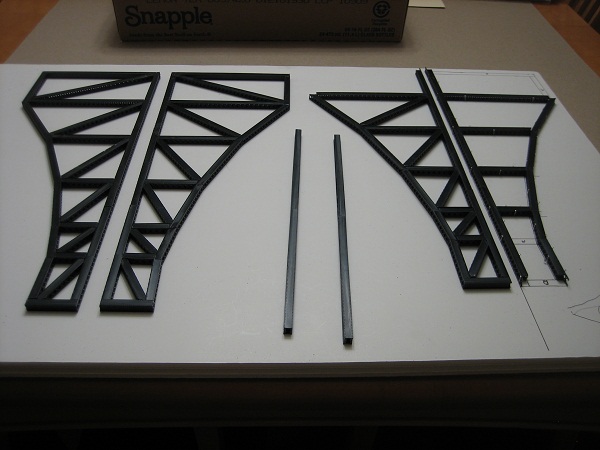
I have worked on the towers a little more. The forth one is almost complete. The bottom of the east tower was left off intentionally so that it can receive the bridge that passes over the other 2 tracks.
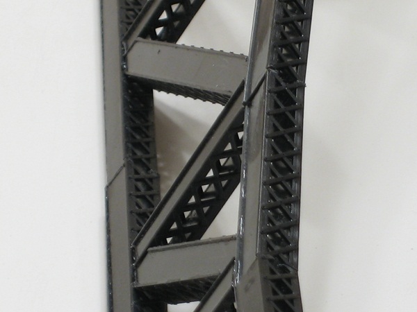
I really like the detail on the bridge girders. Once the towers are freestanding I will work on some splice plates where the girders meet.
My other car is a locomotive, ARHS restoration crew
Posts: 3,683
Threads: 118
Joined: Jan 2009
e-paw Wrote:I have been a member of IBEW local #164 since 8/99 and 827 from 2 years before that.

I knew that! LU716 for me, remember?!

I like the bridge girder detail also. This bridge is going to be tremendous.
Three Foot Rule In Effect At All Times
 now) it to drill two holes in each end that a section of 3/4 or 1 inch pvc pipe that is a tap in fit while its assembled ,to disassemble just tap pipe out. works well if your not moving the section too often.
 now) it to drill two holes in each end that a section of 3/4 or 1 inch pvc pipe that is a tap in fit while its assembled ,to disassemble just tap pipe out. works well if your not moving the section too often.


