Posts: 2,724
Threads: 160
Joined: Dec 2008
You know that Gary, but I wouldn't want someone else trying this same type of thing and either getting hurt or setting there home on fire. Just wanted the other members to know that this is not something to take lightly. ALLWAYS check your contractors credentials before they work on your home or business.
My other car is a locomotive, ARHS restoration crew
Posts: 3,683
Threads: 118
Joined: Jan 2009
Right on, E-paw! 
Now get back to working on that bridge! 
Three Foot Rule In Effect At All Times
Posts: 2,724
Threads: 160
Joined: Dec 2008
As per Gary's suggestion I did some more work to the bridge. 
Now it is time to start the the section that crosses the 2 track main that parallels the river. Just as before I measured and drew out a template of what I needed.
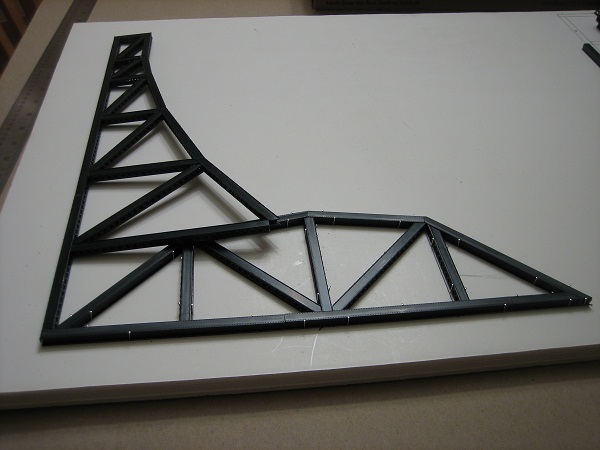
And built the section like my plains.
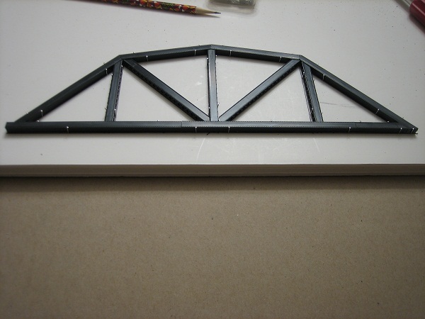
To illustrate the look that I'm going for I placed the tower side roughly in position for the next pic.
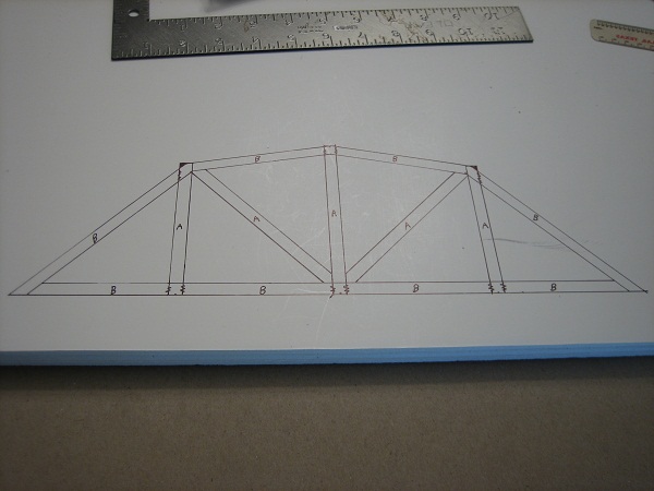
This bridge section is just over 100 feet long and 30 feet tall in the center. Unlike the towers there will be no splice plates at the joints so my seams are much tighter.
My other car is a locomotive, ARHS restoration crew
Posts: 3,683
Threads: 118
Joined: Jan 2009
How come no splice plates on the bridge section? Seems like it would have them. As for the tower splice plates, how will you do the rivets?
Three Foot Rule In Effect At All Times
Posts: 2,724
Threads: 160
Joined: Dec 2008
in the prototype pic I am using as a guide, there only splice plates on the towers and lift section, Don't know why. the plates will be of thin styrene, I'll use a NWSL riveter to make the rivets , like I did on the tanks.
My other car is a locomotive, ARHS restoration crew
Posts: 2,724
Threads: 160
Joined: Dec 2008
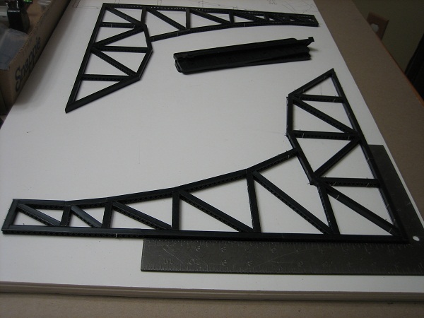
once the 2 bridge sections were dry enough I grabbed a square, lined up the bridge truss and the towers, marked where they intersected, and made my cuts.
I got very that the splices fit on the first try.
I should post a pic of what I am using as a guide. If you check my tread on the Newark bay draw, <!-- l --><a class="postlink-local" href="http://www.the-gauge.net/forum/viewtopic.php?f=26&t=2112">viewtopic.php?f=26&t=2112</a><!-- l --> you will see a pic that I posted on DEC.1st . I was wrong to say there were no splice plates on the smaller truss sections, the pic clearly shows 3 on each side. I may or may not add them, don't know yet.
My other car is a locomotive, ARHS restoration crew
Posts: 1,797
Threads: 81
Joined: Dec 2008
Definitely an ambitious project. Looking forward to see how this turns out. 
Posts: 614
Threads: 14
Joined: Dec 2008
Posts: 2,724
Threads: 160
Joined: Dec 2008
Got sidetracked for a while, but did some more work on the bridge.
I added the through girder section on the part of the bridge that crosses the 2 track line along the river. It was a left over part from my parts box , I think it's a Central Vally part and it fit perfectly. 
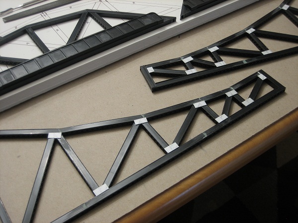
The next tedious part was the splice plates. I cut them out of styrene and embossed rivets with my NWSL riveter.
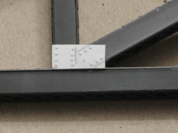
As you can see ther will be a lot of them.
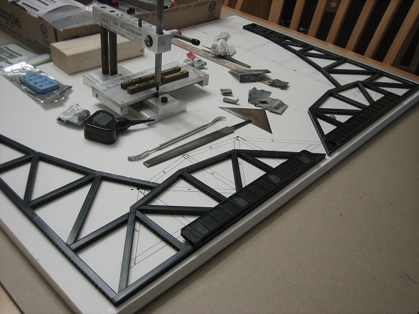
My other car is a locomotive, ARHS restoration crew
Posts: 3,683
Threads: 118
Joined: Jan 2009
Hey, now I know what a riveter looks like! And that's alot of rivets too! Looking good!
Three Foot Rule In Effect At All Times
Posts: 1,817
Threads: 27
Joined: Dec 2009
Kool! I always wanted one of them!
When I get around to building wrappers for the two tenders I have partially built, maybe I'll swallow hard and order one. (As a flakey, see-both-sides-of every-situation ADD-riddled, OCD-impaired Libra, I can justify almost anything if I really want it and have an immediate use for it.)
biL
Lehigh Susquehanna & Western
"America will never be destroyed from the outside. If we falter and lose our freedoms, it will be because we destroyed ourselves." ~~Abraham Lincoln
Posts: 2,724
Threads: 160
Joined: Dec 2008
Well I started on the splice plates for the other tower( I'll call it the east tower) and the bridge.
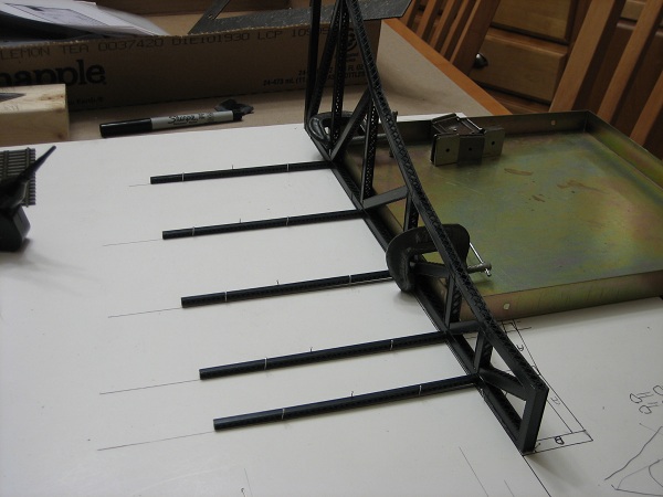
while that dries I drew out and glued up the horizontal sections that will tie the two side sections together.
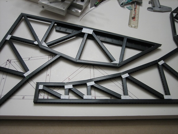
This side will be the west tower.
My other car is a locomotive, ARHS restoration crew
Posts: 2,724
Threads: 160
Joined: Dec 2008
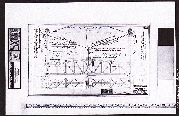
I got this drawing from the library of congress website. It shows the 299 foot lift section of CNJ's Newark bay draw, I will model my lift section after it.
I need a name for this bridge, and I am looking for suggestions.Tomustang came up with a name that was almost unpronounceable  , I believe Mountain Goat Greg called it EP draw in the chat room one day. I'll give you a little background on the layout to help with an appropriate name. Ti is basically a point to point running from Riegelsville PA on the Delaware river in the east to Catawissa pa on the Susquehanna river in the west. This bridge does two things. It joins the two ends of the layout to provide continuous running and represent both river crossing at the same time.
So throw some ideas at me...
My other car is a locomotive, ARHS restoration crew
Posts: 1,992
Threads: 81
Joined: Dec 2008
Modeling New Jersey Under the Wire 1978-1979.
![[Image: logosmall.png]](http://i543.photobucket.com/albums/gg445/CAB_IV/Model%20Trains%202013/logosmall.png)
Posts: 709
Threads: 35
Joined: Jun 2010
Isn't it obvious....
The Delehanna Draw....OR DH for short
Or maybe the
Susqueware...aka the Square Bridge....This will complete confuse everyone as the bridge is in no way square
You could just out a label with Bridge to the 2nd power....
Ok who's next???
|


 , I believe Mountain Goat Greg called it EP draw in the chat room one day. I'll give you a little background on the layout to help with an appropriate name. Ti is basically a point to point running from Riegelsville PA on the Delaware river in the east to Catawissa pa on the Susquehanna river in the west. This bridge does two things. It joins the two ends of the layout to provide continuous running and represent both river crossing at the same time.
![[Image: 400px-HAER-DelairBridge-pa24.jpg]](http://upload.wikimedia.org/wikipedia/commons/thumb/f/f1/HAER-DelairBridge-pa24.jpg/400px-HAER-DelairBridge-pa24.jpg)
![[Image: 800px-DelairandBBbridges.jpg]](http://upload.wikimedia.org/wikipedia/en/thumb/f/f5/DelairandBBbridges.jpg/800px-DelairandBBbridges.jpg)
![[Image: page68_1.jpg]](http://www.workshopoftheworld.com/richmond_bridesburg/delair_files/page68_1.jpg)
![[Image: logosmall.png]](http://i543.photobucket.com/albums/gg445/CAB_IV/Model%20Trains%202013/logosmall.png)