Posts: 1,682
Threads: 101
Joined: Dec 2011
Interesting technic. I can't hardly wait to see the finish result. Your previous camelback is a keeper!
Matt
Posts: 2,724
Threads: 160
Joined: Dec 2008
Thanks Sailormatlac.
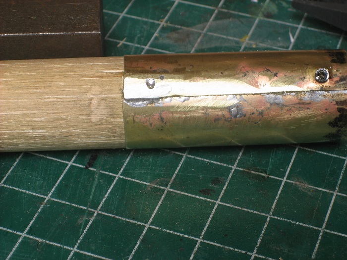
Next the screws are removed and the holes filled with solder. This was also done one at a time just in case the iron loosened the seam while filling the holes.
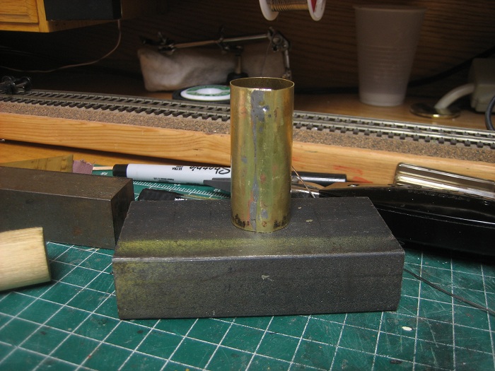
Once that it's all filled run a file over the seam to smooth it out and clean off any excess solder.
Now just pull the sleeve off the dowel and your ready for boiler #2. This yields a pretty nice seam when complete, but still this will end up at the bottom of the boiler so any imperfections will not show.
My other car is a locomotive, ARHS restoration crew
Posts: 2,724
Threads: 160
Joined: Dec 2008
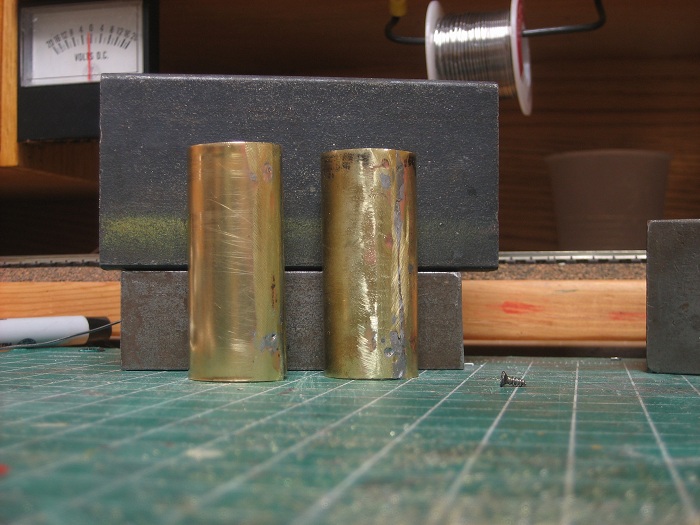
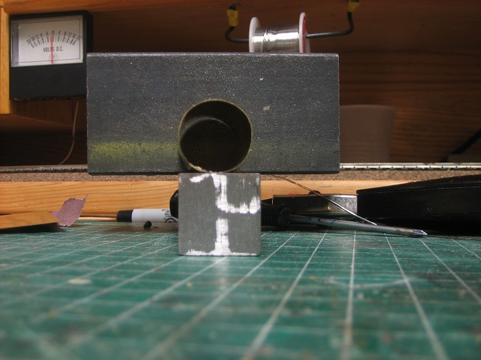
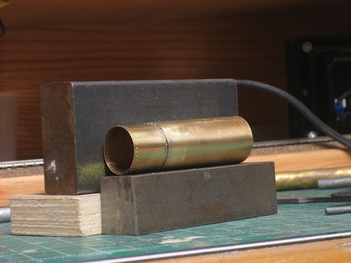
Here's a few pics of the finished product. Nice and round with a strong solder bond.
My other car is a locomotive, ARHS restoration crew
Posts: 1,682
Threads: 101
Joined: Dec 2011
Looks good so far. Is there a specific reason why you make your boilers in brass? My first reflex would be to use a copper or plastic tube. Is it to match the correct diameter?
Matt
Posts: 2,724
Threads: 160
Joined: Dec 2008
Matching the proper diameter is one reason, Matt, and thinner wall that I get by using brass requires less heat for soldering than say copper plumbing pipe. It's also a lot stronger that plastic.
My other car is a locomotive, ARHS restoration crew
Posts: 5,859
Threads: 175
Joined: Dec 2008
Nice work, Steve. 
To avoid having previously soldered work come unsoldered while soldering nearby, cover the joints to be protected with wads of wet tissues or paper towels. It works well when soldering with an iron or torch, and should be even better when using resistance soldering.
It will also allow you to solder right next to plastic, as on this tender ladder.
![[Image: BeegBoy99.jpg]](http://i23.photobucket.com/albums/b399/doctorwayne/CNR%20BEEG%20BOY/BeegBoy99.jpg)
The uprights are attached to the plastic tender with brass pins and had to be installed first, as the ladder rungs are curved. I protected the solder joints between the uprights and the pins and the contact points between the pins and the plastic tender using this method. As each curved rung was soldered in place, it in turn was protected with more wet tissue, resulting in a strong and firmly-attached ladder.
Wayne
Posts: 990
Threads: 47
Joined: Jan 2009
e-paw,
very nice and interest to me seeing your step-by-step documenting building a new engine!
I must say that I would not have courage enough starting such a project. I'm very interested to see next steps and wish you success on the way to a unique model.
Cheers, Bernd
Please visit also my website www.us-modelsof1900.de.
You can read some more about my model projects and interests in my chronicle of facebook.
Posts: 720
Threads: 53
Joined: Dec 2008
The next time I need to roll a boiler, I think I'll try overlapping it after seeing your results. Very well done!
Michael
My primary goal is a large Oahu Railway layout in On3
My secondary interests are modeling the Denver, South Park, & Pacific in On3 and NKP in HO
<!-- m --><a class="postlink" href="http://thesouthparkline.blogspot.com/">http://thesouthparkline.blogspot.com/</a><!-- m -->
Posts: 2,724
Threads: 160
Joined: Dec 2008
I started on the smoke box yesterday. normally the smokebox is unlagged and therefore a slightly smaller diameter than the rest of the boiler. Some people will make a wrapper the same way I will, but layer it on top of the boiler. This to me is just looks plain wrong, because the smokebox is now larger than the boiler. I on the other hand, make the wrapper slightly longer than it needs to be and insert it into the front of the boiler. This yields a much more prototypical appearance.
So here we go. The finished length of the smokebox is 6 feet. I cut a strip of the same brass to a scale 42 feet by a little over 6 feet. This we allow me to press in the rivets for both boxes on one strip, It's a little easier to handle that way. I than use a black marker to color in the approximate location of the front row of rivets. This set of rivets is just a single straight line just before the boiler front. On most locos the spacing is around 4 inches between the rivets. I scribed a line in the ink and marked it in roughly 4 in increments, this will become the inside of the smokebox.
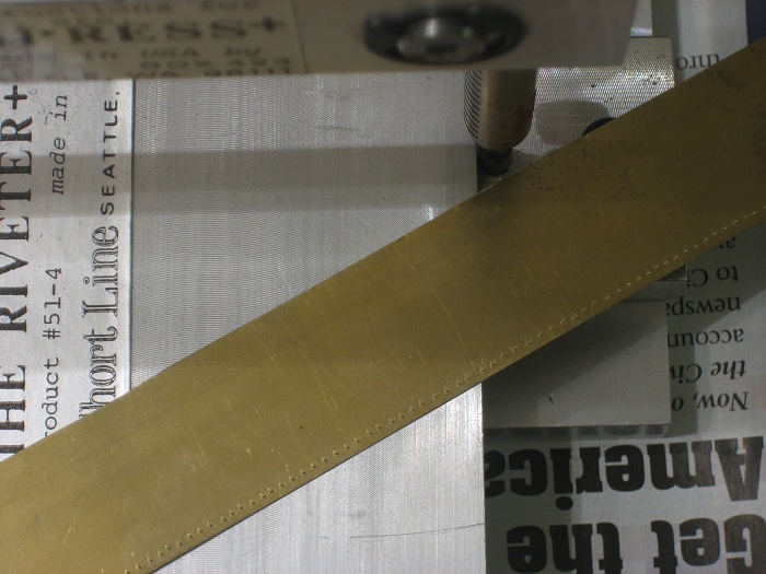
The finished line looks like this.
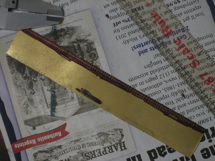
It may not be perfect but it will not be to noticeable once the strip is rounded into shape.
My other car is a locomotive, ARHS restoration crew
Posts: 2,724
Threads: 160
Joined: Dec 2008
I marked out the rear row of rivets the same way as the front. the only difference is that it is actually 2 rows of staggered rivets. Most of the brass past this group of rivets will be soldered inside of the boiler tube.
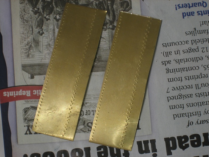
I cut this in half to make the 2 sections that I need for both engines.
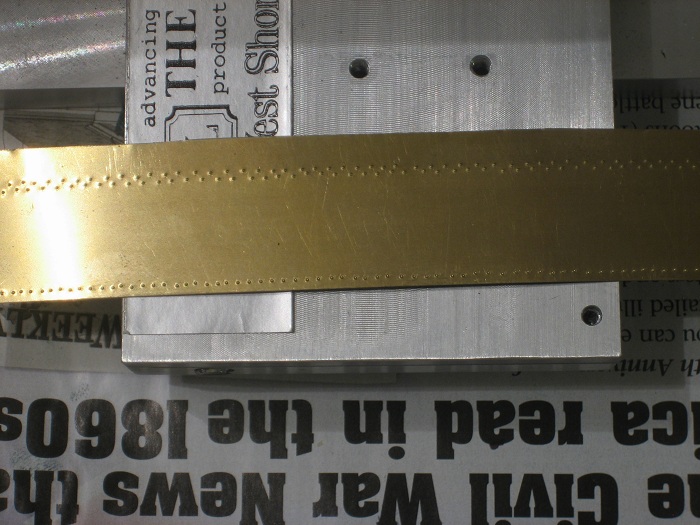
They were then rolled up and placed inside the boiler tubes to rest & conform to a rounded shape, this will make it easier to solder them up tomorrow.
My other car is a locomotive, ARHS restoration crew
Posts: 2,724
Threads: 160
Joined: Dec 2008
Time to install the smokebox....
To prep the smokebox to be soldered in place I marked the aria that would be covered by the overlap and removed the rivets with a file that would be covered by the other side of the wrapper.
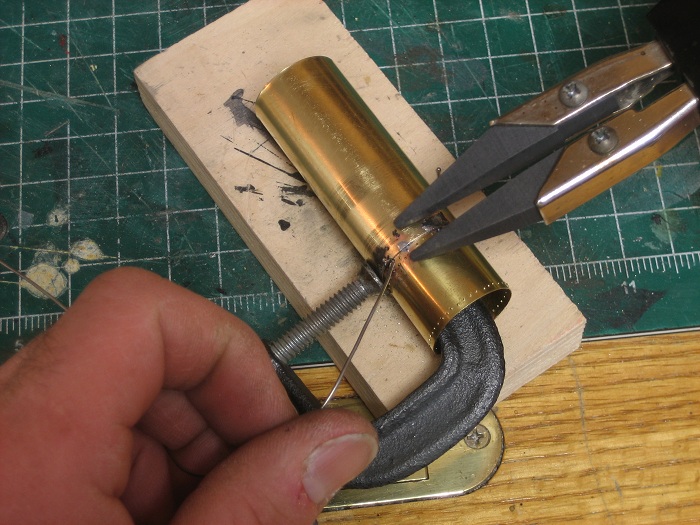
I also cleaned the marker from the arias to be soldered to insure a good bond.
Using my mark as a guide I clamped and tacked the smoke box into a rough shape with some solder. This solder joint is only temporary and will be removed shortly, so I didn't go crazy with it. It is only there to hold the smokebox from twisting as you solder it to the boiler.
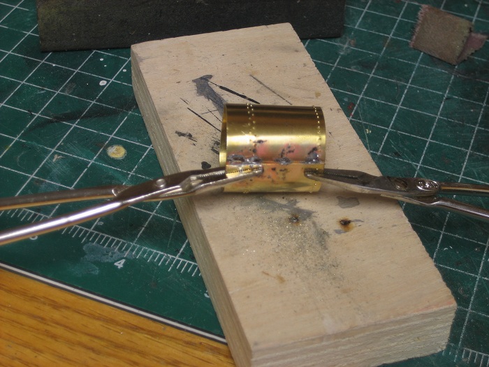
I lined up the smokebox with the seam at the bottom and clamped it in place with a small "C" clamp.
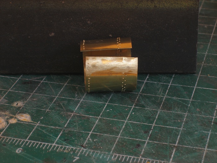
working my way around with the clamp and soldering probes I tacked the smoke box to the boiler. At about the half way point as I went around the seam I un-tacked the bottom solder joint on the overlapping seam. The other solder joints will now hold the smokebox in line. This is done also to keep a "bubble" from forming between the boiler and smokebox. You just keep going around till you get to the bottom and re-solder the overlapping seam with a permanent bond.
Just try to keep the solder to a minimum on the joint between the boiler and smoke box,, it just becomes more to remove latter.
My other car is a locomotive, ARHS restoration crew
Posts: 2,724
Threads: 160
Joined: Dec 2008
After I cleaned off the excess solder I ended up with this, a completed, round boiler and smokebox section. 
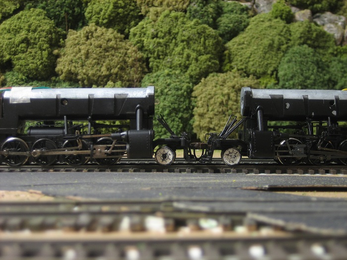
I will start on the boiler front only after enough of the boiler is completed so that I figure out how I will mount it to the frame, other wise it will just be in the way.
One other thing that I wanted to address today is the front pilot wheels, they are of an older spoked style. I am going for a mid 40's look, so they just won't do. Once again I'm going back to a method that I used on my K-1as witch had the same kind of pilot wheels. Very simply fill in the spokes with body putty and sand them to shape. It worked well on the 4-8-0 so I'm using it again.
This is the first of several applications of putty, when it dries It will get sanded and more putty added.
My other car is a locomotive, ARHS restoration crew
Posts: 1,682
Threads: 101
Joined: Dec 2011
Very interesting work. Looks so simple when looking at this boiler!
Matt
Posts: 5,859
Threads: 175
Joined: Dec 2008
e-paw Wrote:After I cleaned off the excess solder I ended up with this, a completed, round boiler and smokebox section.
Very nicely done. 
Wayne
Posts: 4,161
Threads: 174
Joined: Dec 2008
That's really impressive!
|


![[Image: BeegBoy99.jpg]](http://i23.photobucket.com/albums/b399/doctorwayne/CNR%20BEEG%20BOY/BeegBoy99.jpg)
